A skilled mountain biker can cross some extreme terrain, but [The Q] thought there might be room for improvement, so he converted a fat bike to all-wheel drive.
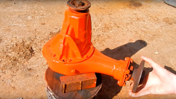
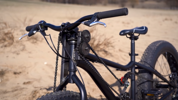
The major challenge here is transferring pedal power to the front wheels, especially around the headset. [The Q] solved this by effectively building a differential from the parts of a very old hand drill. Since the front wheel needs to rotate at the same speed as the rear, one long chain loops from the rear wheel to the headset, tensioned by a pair of derailleurs. This front sprocket turns a series of spur gears and bevel gear arranged around the headset, which transfers the power down to the front wheel via another chain.
It would be interesting to feel what the bike rides like in soft sand, mud, and over rocks. We can see it has some advantages in those conditions but were unsure if it would be enough to offset the penalty in weight and complexity. The additional chains and gears certainly look like they’re asking to catch foliage, clothing, and maybe even skin. However, we suspect [The Q] was more likely doing it for the challenge of the build, which we can certainly appreciate. With the rise of e-bikes, adding a hub motor to the front wheel seems like a simpler option.
We’ve seen several interesting bicycle hacks over the years, including a strandbeest rear end, 3D printed tires and an automatic shifter. Continue reading “All-Wheel Drive Bicycle Using Hand Drill Parts”