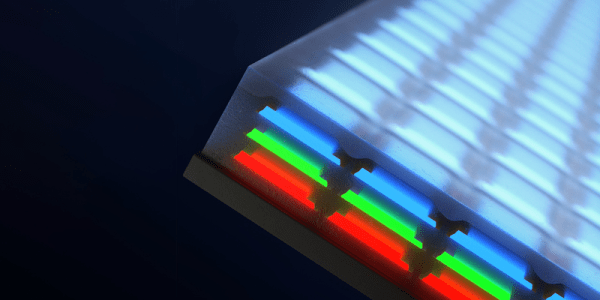
A Well Documented BreadBoard Computer Shows Dedication

These pages have not been exactly devoid of home-built computers, with those constructed on solderless breadboard less frequent, but still not rarities. But what is more of a rarity is this ground-up 8-bit 74xx logic-based computer (video, embedded below) with full source, an emulator, assembler and test suite. [JDH] spent a solid couple of weeks working late into the night to build this, and the results show for themselves.

The new JDH-8 is now a figment of reality.

The architecture is a traditional 8-bit load/store microcoded processor with the microcode stored in easily programmable AT28C64 EEPROMs for ease of tweaking.  The address bus is 16-bits, which is quite ample for this, and puts it in line with (admittedly more sophisticated) 8-bit micros of old such as the 6502. There is also a hardware stack, and a discrete-logic ALU as well! Finally, since that wasn’t enough work already, he added in his own discrete logic video controller.

Wise people simulate before prototyping something like this

There are sixteen instructions covering memory access, ALU operations and I/O operations. One of the great things about this project is that [JDH] readily admits the mistakes made along the way, and how the architecture didn’t need to be this complex. One example is that hardware stack wasn’t really necessary as it could just have been implemented in software. Also, due to the implementation, memory accesses were so fast compared with the achievable cycle time, that there really was no point to using load/store architecture at all! Still, [JDH] had fun building and programming it!

It was interesting to see the use of LogiSim-Evolution to debug first a high level model of the architecture and then the translation into TTL chips. This scribe wasn’t aware of that tool (the shame!) but is going to try this out real soon.

All code for the software side of things can be found on the project GitHub. Perhaps the hardware design will appear there as well, be at the time of writing we couldn’t seem to find it.

Can’t get enough breadboard computers? (We can’t) check this out from last year. Stuck for a suitable enclosure for your latest bread breadboard computer? How about a bread bin.

Continue reading “A Well Documented BreadBoard Computer Shows Dedication”

Marble-elevator dot-matric display

Simple Design Elevates This Mechanical Dot Matrix Display

Don’t get us wrong — we love unique displays as much as anyone. But sometimes we stumble across one that’s so unique that we lack the basic vocabulary to describe it. Such is the case with this marble-raising dot-matrix alphanumeric display. But it’s pretty cool, so we’ll give it a shot.

The core — literally — of [Shinsaku Hiura]’s design is a 3D-printed cylinder with a spiral groove in its outside circumference. The cylinder rotates inside a cage with vertical bars; the bars and the grooves are sized to trap 6-mm AirSoft BBs, which are fed into the groove by a port in the stationary base of the display. BBs are fed into the groove at the right position to form characters, which move upwards as the cylinder rotates. Just watch the video below — it explains it far better than words can.

The clever bit is how the BBs are fed into the groove. Rather than have a separate mechanism to gate the feed port, there’s a backlash mechanism that opens the port when the motor powering the drum runs in reverse for a bit. It’s a clever use of cams to get the job done without adding an extra servo, which sort of reminds us of the design parsimony exhibited in his one-servo seven-segment display.

It’s not clear that this would be a very practical display, but that doesn’t stop it from being cool. Although, [Shinsaku Hiura] just released a follow-up video showing a bigger version of this used to display upcoming events from Google Calendar, so perhaps we’re wrong. Continue reading “Simple Design Elevates This Mechanical Dot Matrix Display”

Mechanical 7-segment display

A One-Servo Mechanical Seven-Segment Display

The seven-segment display may be a bit prosaic after all these years, but that doesn’t mean there aren’t ways to spice it up. Coming up with a mechanical version of the typical photon-based display is a popular project, of which we’ve seen plenty of examples over the years. But this seven-segment display is quite a mechanical treat, and a unique way to flip through the digits.

With most mechanical displays, we’re used to seeing the state of each segment changed with some kind of actuator, like a solenoid or servo. [Shinsaku Hiura] decided on a sleeker design using a 3D-printed barrel carrying one cam for each segment. Each hinged segment is attached to an arm that acts as a follower, riding on its cam and flipping on or off in a set pattern. Which digit is displayed depends on the position of the barrel, which is controlled with a single servo and a pair of gears. It trades mechanical complexity for electrical simplicity and overall elegance, and as you can see from the video below, it’s pretty snappy.

We think the best part of this build is figuring out the shape of the cams. We wonder how they compare to the cam profiles in [Greg Zumwalt]’s mechanical display; it uses two separate discs with grooves, but the principle is pretty much the same.

Continue reading “A One-Servo Mechanical Seven-Segment Display”

mechanical seven segment display

Mesmerizing Mechanical Seven-Segment Display

Seven-segment displays are ubiquitous. From where I’m writing this, I can see several without even having to swivel my chair. We’re all familiar with their classic visage; slightly italicized numbers that are brought to life by LEDs. There are a boatload of variants available– you can get displays with a decimal point, ones with multiple numbers, and even versions in just about any color you desire, but at the core they’re all basically the same thing- an array of LEDs sitting behind a faceplate. Except for those ones that have some gears inside.

Wait, what?

You read that right– a seven-segment display that contains gears, along with a handful of cams for good measure. Artist [Kango Suzuki] created this stunning all-mechanical seven-segment display that sequentially counts up from zero to nine when a thumbwheel is spun. All of the components are cut from wood and mesh together beautifully, complete with a satisfying click when the display rolls into a new digit, which you can hear in the video at the above link. You may recognize [Kango]’s style from this incredible mechanical clock he made a few years back. Unlike his earlier work, the seven-segment display is tiny, relatively speaking. Maybe we’ll see it integrated into a larger project some day, like a mechanical-digital clock.

We just love when somebody uses intricate mechanisms to artfully emulate some piece of existing tech. This isn’t even the first time we’ve seen a mechanical seven-segment display; [Peter Lehnér] built one back in 2019, and judging by [Kango]’s twitter feed, it appears to have inspired his design. There have even been a few other 3D printed ones over the years, but as far as we know this is the first wooden one– and, in true [Kango] fashion, its beautiful.

Thanks to [J. Peterson] for the tip!

Continue reading “Mesmerizing Mechanical Seven-Segment Display”

Fetch ferrofluid display

Ferrofluid Display Gets New, Better Driver Circuitry

In 2019 [Simen] and [Amud], two students from the University of Oslo, set out to design a unique open-source display. The result was Fetch, a display that uses electromagnets to suspend ferrofluid on 252 “pixels” across the screen. After some delays due to COVID, they have recently unveiled version 2.0 of the display on their project’s page.

While the duo managed to overcome the mechanical challenges associated with using ferrofluids fairly easily, they were quickly bottlenecked by their electronics. The use of electromagnets holding up a liquid presented a unique challenge; the magnets could not be switched off, even for a millisecond, or else the “pixel” would fall down to the bottom of the screen. That immediately ruled out any sort of multiplexing and meant everything would have to be driven in parallel. As if that wasn’t already difficult enough to work around, the effect of having multiple electromagnets activated next to each other would change how the ferrofluid flows. This meant that the strength of each electromagnet would have to be adjusted based on what is currently being displayed, rather than just being on or off.

The mess of connections were not helped with the layout of the old driver boards shown here. The new design puts the connections closer to each individual electromagnet.

All of this, paired with other overhead like generating pulse-width modulation for the inputs, was just too much for a single microcontroller to handle. So, the pair set out to design a better version of their electronics that would offload a lot of the hard work. At the same time, they decided a bit of mechanical optimization was in order; they redesigned the boards to be longer and thinner, allowing them to fit cleanly behind the row of electromagnets they controlled.

The new boards feature a PCA9685 IC, which allows for the control of up to 16 channels of 12-bit PWM over i2C, perfect for the size of the display. Since this IC can’t source enough current to drive the electromagnets, it was paired with a ULN2803 Darlington Transistor Array, capable of delivering up to 500mA to each electromagnet.

With prototypes in hand (and a few bodge wires here and there), [Simen] and [Amud] had the new driver boards running beautifully, displaying text in a mesmerizing way that no ordinary display could match. Watch the video after the break for a demonstration of the new controllers in action, as well as a deeper dive into the process of developing them.

Want to learn more? Check out our previous article about Fetch! Or if you’re looking for another cool way to use ferrofluids, how about making it dance in a custom speaker!

Continue reading “Ferrofluid Display Gets New, Better Driver Circuitry”

PNG Image Decoding Library Does It With Minimal RAM

Want to display a PNG file on a display attached to an Arduino or other microcontroller board? You’ll want to look at [Larry Bank]’s PNGdec, the Arduino-friendly PNG decoder library which makes it much easier to work with PNG files on your chosen microcontroller.

The PNG image format supports useful features like lossless compression, and was generally developed as an improved (and non-patented) alternative to GIF files. So far so great, but it turns out that decoding PNG files on a microcontroller is a challenge due to the limited amount of memory compared to desktop machines. When the PNG specification was developed in the 90s, computers easily had megabytes of memory to work with, but microcontrollers tend to have memory measured in kilobytes, and lack high-level memory management. [Larry]’s library addresses these issues.

PNGdec is self-contained and free from external dependencies, and also has some features to make converting pixel formats for different display types easy. It will run on any microcontroller that can spare at least 48 K of RAM, so if that sounds useful then check out the GitHub repository for code and examples.

We’ve seen [Larry]’s wonderful work before on optimizing GIF playback as well as rapid JPEG decoding, and these libraries have increasing relevance as hobbyists continue to see small LCD and OLED-based displays become ever more accessible and affordable.

[PNG logo: PNG Home Site]

A Mini USB Display For Your PC Desktop

By now it’s likely that most Hackaday readers will be used to USB display adapters, in their most common form channeling DisplayPort over the ubiquitous serial interface. Connecting to projectors and other screens with a laptop becomes a breeze, and gone are the days of “Will my laptop work in the venue” stress for people delivering presentations. [Avra Mitra]’s STM32 tiny monitor may not ascend to these giddy heights, but it does at least live up to the promise of reproducing a desktop onto a small colour LCD hooked up through a USB port.

Not through any DisplayPort wizardry though, instead it relies on a Python script that takes successive screen grabs and streams them through USB to the microcontroller, which in tun puts them on the display. It’s claimed to achieve 6 to 7 frames per second as you can see in the video below, with an admission that there remains a huge scope for improvement.

Notwithstanding its limited utility at the moment, we can see that maybe this idea could have its uses in a very basic display after a few improvements. Meanwhile, more conventional monitors take the established route of pairing a dedicated controller board with an LCD panel.

Continue reading “A Mini USB Display For Your PC Desktop”