Sometimes a successful project isn’t only about making sure all the electrons are in the right place at the right time, or building something that won’t collapse under its own weight. A lot of projects involve a fair amount of social engineering to be counted as a success, especially those that might result in arrest and incarceration if built as originally planned. Such projects are often referred to as “the fun ones.”
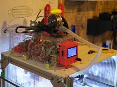
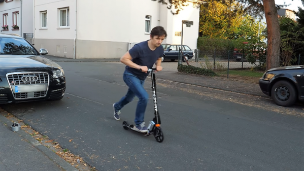
For the past few months, we’ve been following [Bitluni]’s DIY electric scooter build, which had been following the usual trajectory for these things – take a stock unpowered scooter, replace the rear wheel with a 250 W hub motor, add an ESC, battery, and throttle, and away you go. Things took a very interesting turn, however, when his street testing ran afoul of German law, which limits small electric vehicles to a yawn-inducing 6 kph. Unwilling to bore himself to death thus, [Bitluni] found a workaround: vehicles that are only assisted by an electric motor have a much more reasonable speed limit of 25 kph. So he added an Arduino with a gyro and accelerometer module and wrote a program to only power the wheel after the rider has kicked the scooter along a few times – no throttle needed. The motor stops after a bit, needing another push or two to kick it back on. A brake lever kills the motor, as does laying the scooter on its side. It’s quite a clever design, and while it might not keep the Polizei at bay, you can’t say he didn’t try.
[Bitluni] has quite a range of builds, from software-defined television to bad 3D-scanners to precision wine glass whacking. You should check out his stuff. Continue reading “Building An Electric Scooter That’s Street Legal, Even In Germany”