We’re not aware of any authoritative metrics on such things, but it’s safe to say that the Ender 3 is among the most hackable commercial 3D printers. There’s just something about the machine that lends itself to hacks, most of which are obviously aimed at making it better at 3D printing. Some, though, are aimed in a totally different direction.
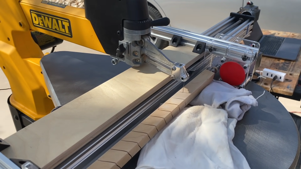
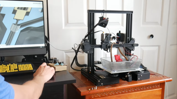
As proof of that, check out this Ender 3 modified for electrochemical machining. ECM is a machining process that uses electrolysis to remove metal from a workpiece. It’s somewhat related to electric discharge machining, but isn’t anywhere near as energetic. [Cooper Zurad] has been exploring ECM with his Ender, which he lightly modified by replacing the extruder with a hypodermic needle electrode. The electrode is connected to a small pump that circulates electrolyte from a bath on the build platform, while a power supply connects to the needle and the workpiece. As the tool traces over the workpiece, material is electrolytically removed.
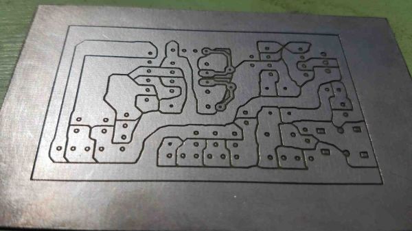
The video below is a refinement of the basic ECM process, which [Cooper] dubs “wire ECM.” The tool is modified so that electrolyte flows down the outside of the needle, which allows it to enter the workpiece from the edge. Initial results are encouraging; the machine was able to cut through 6 mm thick stainless steel neatly and quickly. There does appear to be a bit of “flare” to the cut near the bottom of thicker stock, which we’d imagine might be mitigated with a faster electrolyte flow rate.
If you want to build your own Ender ECM, [Cooper] has graciously made the plans available for download, which is great since we’d love to see wire ECM take off. We’ve covered ECM before, but more for simpler etching jobs. Being able to silently and cleanly cut steel on the desktop would be a game-changer.
Continue reading “Simple Mods Turn 3D Printer Into Electrochemical Metal Cutter”