Wave Drive Made With 3D Printed Parts

You can get just about any gear reduction you want using conventional gears. But when you need to get a certain reduction in a very small space with minimal to no backlash, you might find a wave drive very useful. [Mishin Machine] shows us how to build one with (mostly) 3D printed components.

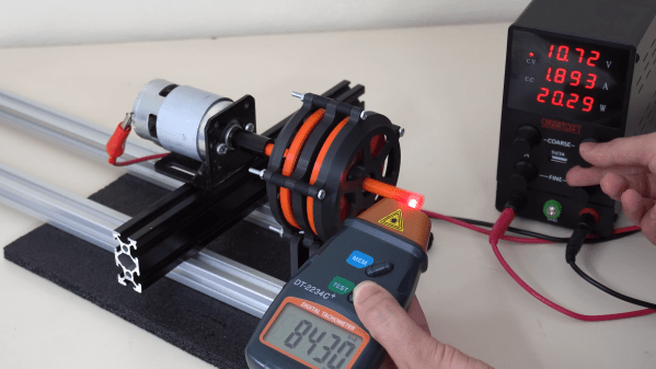
The video does a great job of explaining the basics of the design. Right off the bat, we’ll say this one isn’t fully printed—it relies on off-the-shelf steel ball bearings. It’s easy to understand why. When you need strong, smooth-rolling parts, it’s hard to print competitive spheres in plastic at home. Plastic BBs will work too, though, as will various off-the-shelf cylindrical rollers. The rest is mostly 3D printed, so with the right design, you can whip up a wave drive to suit whatever packaging requirements you might have.

Combined with a stepper motor and the right off-the-shelf parts, you can build a high-reduction gearbox that can withstand high torque and should have reasonable longevity despite being assembled with many  printed components.

We’ve seen other interesting gear reductions before, too.

Continue reading “Wave Drive Made With 3D Printed Parts”

Wire-frame image of gearbox, setup as a differential

Roller Gearbox Allows For New Angles In Robotics

DIY mechatronics always has some unique challenges when relying on simple tools. 3D printing enables some great abilities but high precision gearboxes are still a difficult problem for many. Answering this problem, [Sergei Mishin] has developed a very interesting gearbox solution based on a research paper looking into simple rollers instead of traditional gears. The unique attributes of the design come from the ability to have a compact angled gearbox similar to a bevel gearbox.

Multiple rollers rest on a simple shaft allowing each roller to have independent rotation. This is important because having a circular crown gear for angled transmission creates different rotation speeds. In [Sergei]’s testing, he found that his example gearbox could withstand 9 Nm with the actual adapter breaking before the gearbox showing decent strength.

Continue reading “Roller Gearbox Allows For New Angles In Robotics”

Bicycle Gearbox Does It By Folding

If you’ve spent any time on two wheels, you’ve certainly experienced the woes of poor bicycle shifting. You hit the button or twist the knob expecting a smooth transition into the next gear, only to be met with angry metallic clanking that you try to push though but ultimately can’t. Bicycle manufacturers collectively spent millions attempting to remedy this issue with the likes of gearboxes, electronic shifting, and even belt-driven bikes. But Praxis believes to have a better solution in their prototype HiT system.

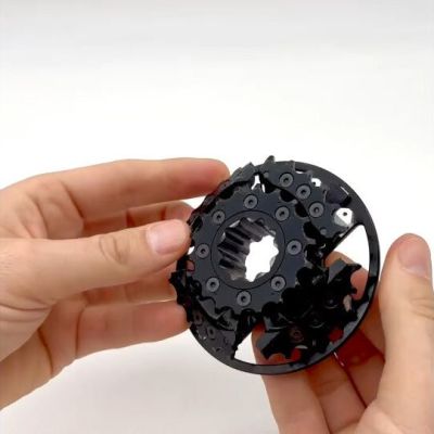
Rather then moving a chain between gears, their novel solution works by folding gears into or away from a chain. These gears are made up of four separate segments that individually pivot around an axle near the cog’s center. These segments are carefully timed to ensure there is no interference with the chain making shifting look like a complex mechanical ballet.

While the shift initialization is handled electronically, the gear folding synchronization is mechanical. The combination of electronic and mechanical systems brings near-instant shifting under load at rotational rates of 100 RPM. Make sure to scroll through the product page and watch the videos showcasing the mechanism!

The HiT gearbox is a strange hybrid between a derailleur and a gearbox. It doesn’t contain a clutch based gear change system or even a CVT as seen in the famous Honda bike of old. It’s fully sealed with more robust chains and no moving chainline as in a derailleur system. The prototype is configurable between four or sixteen speeds, with the four speed consisting of two folding gear pairs connected with a chain and the sixteen speed featuring a separate pair of folding gears. The output is either concentric to the input, or above the input for certain types of mountain bikes.

Despite the high level of polish, this remains a prototype and we eagerly await what Praxis does next with the system. In the meantime, make sure to check out this chainless e-drive bicycle.

Behold A Geared, Continuously Variable Transmission

When it comes to transmissions, a geared continuously-variable transmission (CVT) is a bit of a holy grail. CVTs allow smooth on-the-fly adjustment of gear ratios to maintain a target speed or power requirement, but sacrifice transmission efficiency in the process. Geared transmissions are more efficient, but shift gear ratios only in discrete steps. A geared CVT would hit all the bases, but most CVTs are belt drives. What would a geared one even look like? No need to wonder, you can see one for yourself. Don’t miss the two videos embedded below the page break.

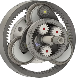
The outer ring is the input, the inner ring is the output, and the three little gears with dots take turns transferring power.

The design is called the RatioZero and it’s reminiscent of a planetary gearbox, but with some changes. Here’s how the most visible part works: the outer ring is the input and the inner ring is the output. The three small gears inside the inner ring work a bit like relay runners in that each one takes a turn transferring power before “handing off” to the next. The end result is a smooth, stepless adjustment of gear ratios with the best of both worlds. Toothed gears maximize transmission efficiency while the continuously-variable gear ratio allows maximizing engine efficiency.

There are plenty of animations of how the system works but we think the clearest demonstration comes from [driving 4 answers] with a video of a prototype, which is embedded below. It’s a great video, and the demo begins at 8:54 if you want to skip straight to that part.

One may think of motors and gearboxes are a solved problem since they have been around for so long, but the opportunities to improve are ongoing and numerous. Even EV motors have a lot of room for improvement, chief among them being breaking up with rare earth elements while maintaining performance and efficiency.

Continue reading “Behold A Geared, Continuously Variable Transmission”

Lathe Outfitted With Electronic Gearbox

Running a metal lathe is not for the faint of heart. Without proper knowledge and preparation, these machines can quickly cause injury or destroy expensive stock, tools, or parts. The other major problem even for those with knowledge and preparedness is that some of their more niche capabilities, like cutting threads with a lead screw, can be tedious and complicated thanks to the change gear system found on some lathes. While these are useful tools for getting things done, [Not An Engineer] decided that there was a better way and got to work building an electronic gearbox to automate the task of the traditional mechanical change gear setup in this video.

What makes change gears so tricky is that they usually come as a set of many gears of different ratios, forcing the lathe operator to figure out the exact combination of gears needed to couple the spindle of the lathe to the feed screw at the precise ratio needed for cutting a specific thread pattern. It is possible to do this task but can be quite a headache. [Not An Engineer] first turned to an Arduino Nano to receive input from a rotary encoder connected to the shaft of the lathe and then instruct a motor to turn the feed screw at a set ratio.

The first major problem was that the Arduino was not nearly fast enough to catch every signal from the encoder, leading to a considerable amount of drift in the output of the motor. That was solved by upgrading to a Teensy 4.1 with a 600 MHz clock speed. There was still one other major hurdle to cross; the problem of controlling the motor smoothly when an odd ratio is selected. [Not An Engineer] used this algorithm to inspire some code, and with that and some custom hardware to attach everything to the lathe he has a working set of electronic change gears that never need to be changed again. And, if you don’t have a lathe at all but are looking to get started with one, you can always build your own from easily-sourced parts.

Continue reading “Lathe Outfitted With Electronic Gearbox”

Magnetic Gearbox, Part 2: Axial Flux Improves Performance

The number of interesting and innovative mechanisms that 3D printing has enabled always fascinates us, and it’s always a treat when one of them shows up in our feeds. This axial flux magnetic gearbox is a great example of such a mechanism, and one that really makes you think about possible applications.

The principles of [Retsetman]’s gearbox are simple for anyone who has ever played with a couple of magnets to understand, since it relies on that powerful attractive and repulsive force you feel when magnets get close to each other. Unlike his previous radial flux gearbox, which used a pair of magnet-studded cylindrical rotors nested one inside the other, this design has a pair of disc-shaped printed rotors that face each other on aligned shafts. Each rotor has slots for sixteen neodymium magnets, which are glued into the slots in specific arrangements of polarity — every other magnet for the low-speed rotor, and groups of four on the high-speed rotor. Between the two rotors is a fixed flux modulator, a stator with ten ferromagnetic inserts screwed into it.

In operation, which the video below demonstrates nicely, the magnetic flux is coupled between the rotors by the steel inserts in the stator so that when one rotor moves, the other moves at a 4:1 (or 1:4) ratio in the opposite direction. [Retsetman] got the gearbox cranked up to about 8,500 RPM briefly, but found that extended operation at as little as 4,000 RPM invited disaster not due to eddy current heating of the inserts or magnets as one might expect, but from simple frictional heating of the rotor bearings.

Torque tests of the original gearbox were unimpressive, but [Retsetman]’s experiments with both laminated stator inserts and more powerful magnets really boosted the output — up to a 250% improvement! We’d also like to see what effect a Halbach array would have on performance, although we suspect that the proper ratios between the two rotors might be difficult to achieve.

Continue reading “Magnetic Gearbox, Part 2: Axial Flux Improves Performance”

A line art schematic of a bicycle CVT drive. Two large green circles at the bottom have the text "1. Increases speed" where the crank arm would enter the system. A series of cam arms highlighted in red say "2. Converts from rotary to reciprocating motion." Finally, a blue highlighted bearing says "3. Converts from reciprocating back to rotary motion."

A Look Inside Bicycle Gearboxes

While bicycle gearboxes date back to at least the 1920s, they’re relatively unseen in bike racing. One exception is Honda’s race-winning mid-drive gearboxes, and [Alee Denham] gives us a look at what makes these unique drives tick.

Honda has developed three generations of bicycle gearbox as part of their company’s R&D efforts, but none have ever been released as a commercial product. Designed as a way for their engineers to stretch their mental muscles, the gearboxes were only used in bike races and seen at a few trade shows. In 2004, the third gen “derailleur in a box” led to the first gearbox victory in the Downhill World Cup Circuit.

The third gen gearbox differs significantly from the CVT drivetrains in the first and second generation gearboxes, but it is unclear why Honda abandoned the CVT. [Denham] has a nice animation detailing the inner workings of these CVTs based on information from the original patents for these rarely seen gearboxes.

Derailleurs remain the primary drivetrain in racing due to their lighter weight and higher overall efficiency. While still expensive, the decreased maintenance of gearbox drivetrains make a lot of sense for more mundane cycling tasks like commuting or hauling cargo, but only time will tell if the derailleur can be supplanted on the track and trail.

For more on bicycle drivetrains, check out this chainless digital drivetrain or the pros and cons of e-bike conversions.

Continue reading “A Look Inside Bicycle Gearboxes”