An Anti-Tamper Mesh Plugin For KiCad

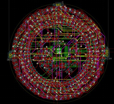
Physical access to electronics generally means all bets are off when it comes to information security. But in special cases this is just unacceptable and a better solution must be found. Consider the encryption keys used by point of sale machines. To protect them, the devices incorporate anti-tamper mechanisms that will wipe the keys from memory if the device is opened. One such technique is to use a mesh of traces on a circuit board that are monitored for any changes in resistance or capacitance. [Sebastian Götte] has been researching in this area and wrote a KiCad plugin to automatically generate tamper-detection mesh.

The idea is pretty simple, place traces very close to one another and it makes it impossible to drill into the case of a device without upsetting the apple cart. There are other uses as well, such as embedding them in adhesives that destroy the traces when pried apart. For [Sebastian’s] experiments he’s sticking with PCBs because of the ease of manufacture. His plugin lays down a footprint that has four pads to begin and end two loops in the mesh. The plugin looks for an outline to fence in the area, then uses a space filling curve to generate the path. This proof of concept works, but it sounds like there are some quirks that can crash KiCad. Consider taking a look at the code if you have the expertise to help make it more stable.

We’ve seen these anti-tamper meshes in practice in the VeriFone payment terminal that [Tom Nardi] tore down a couple of years ago. The approach that [Sabastian] took with the plugin actually produces a more complex mesh than was in use there as it only really used vertical lines for the traces.

Peek Into This Synth’s Great Design (And Abandoned Features)

[Tommy]’s POLY555 is an analog, 20-note polyphonic synthesizer that makes heavy use of 3D printing and shows off some clever design. The POLY555, as well as [Tommy]’s earlier synth designs, are based around the 555 timer. But one 555 is one oscillator, which means only one note can be played at a time. To make the POLY555 polyphonic, [Tommy] took things to their logical extreme and simply added multiple 555s, expanding the capabilities while keeping the classic 555 synth heritage.

The real gem here is [Tommy]’s writeup. In it, he explains the various design choices and improvements that went into the POLY555, not just as an instrument, but as a kit intended to be produced and easy to assemble. Good DFM (Design For Manufacturability) takes time and effort, but pays off big time even for things made in relatively small quantities. Anything that reduces complexity, eliminates steps, or improves reliability is a change worth investigating.

For example, the volume wheel is not a thumbwheel pot. It is actually a 3D-printed piece attached to the same potentiometer that the 555s use for tuning; meaning one less part to keep track of in the bill of materials. It’s all a gold mine of tips for anyone looking at making more than just a handful of something, and a peek into the hard work that goes into designing something to be produced. [Tommy] even has a short section dedicated to abandoned or rejected ideas that didn’t make the cut, which is educational in itself. Want more? Good news! This isn’t the first time we’ve been delighted with [Tommy]’s prototyping and design discussions.

POLY555’s design files (OpenSCAD for enclosure and parts, and KiCad for schematic and PCB) as well as assembly guide are all available on GitHub, and STL files can be found on Thingiverse. [Tommy] sells partial and complete kits as well, so there’s something for everyone’s comfort level. Watch the POLY555 in action in the video, embedded below.

Continue reading “Peek Into This Synth’s Great Design (And Abandoned Features)”

Open-Source Thermostat Won’t Anger Your Landlord

[Nathan Petersen] built a Hackable Open-Source Thermostat to smooth out temperature fluctuations caused by the large hysteresis of the bimetallic strip thermostat in his apartment. While it may be tempting to adjust the “anticipator” to take care of the problem or even replace the bimetallic thermostat with an electronic version, building your own thermostat from scratch is a good way to add to your project portfolio while making your way through college. Plus, he got to hone his hardware and software design chops.

The hardware is designed around the STM32, using a cheap, minimal variant since the device just needs to sense temperature and control the furnace in on-off mode. The TMP117 high-accuracy, low-power, temperature sensor was selected for temperature measurement since accuracy was an essential feature of the project. Dry-contact output for the furnace is via a normally-open solid state relay (opto-isolator). For the user interface, instead of going the easy-route and using an I2C/SPI OLED or LCD display, [Nathan] used three 7-segment LED displays, each driven by an 8-channel constant current driver. The advantage is that the display can be viewed from across the room, and it’s brightness adjusted via PWM. Temperature set-point adjustment is via a simple slide potentiometer, whose analog voltage is read by the micro-controller ADC. To remind about battery replacement, a second ADC channel on the micro-controller monitors the battery voltage via a voltage divider. The PCB components are mostly surface mount, but the packages selected are easy enough to hand solder.

[Nathan]’s Github repo provides the hardware and firmware source files. The board is designed in Altium, but folks using KiCad can use either the awesome Altium2KiCad converter or the online service for conversion. (The results, with some minor errors that can be easily fixed, are quite usable.) Serendipitously, his PCB layout worked like a charm the first time around, without requiring any rework or bodge wires.

The firmware is a few hundred lines of custom bare-metal C code, consisting of drivers to interface with the hardware peripherals, a UI section to handle the user interface, and the control section with the algorithm for running the furnace. [Nathan] walks us through his code, digging into some control theory and filtering basics. After making a few code tweaks and running the thermostat for some time, [Nathan] concludes that it is able to achieve +0.1°F / -0.5°F temperature regulation with furnace cycles lasting about 10-15 minutes (i.e. 4-6 cycles per hour). Obviously, his well insulated apartment and a decent furnace are also major contributing factors. Moving on, for the next version, [Nathan] wants to add data collection capabilities by adding some memory and SD card storage, and use an RTC to allow seasonal adjustments or time-based set-points.

This is his first attempt at a “functional’ useful project, but he does love to build the occasional toy, such as this POV Top.

Feeling The KiCad 6 Electricity

In 2018, when KiCad Version 5 modernized the venerable 4.X series, it helped push KiCad to become the stable and productive member of the open source EDA landscape that we know today. It has supported users through board designs both simple and complex, and like a tool whose handle is worn into a perfect grip, it has become familiar and comfortable. For those KiCad users that don’t live on the bleeding edge with nightly builds it may not be obvious that the time of version 6 is nearly upon us, but as we start 2021 it rapidly approaches. Earlier this month [Peter Dalmaris] published a preview of the changes coming version 6 and we have to admit, this is shaping up to be a very substantial release.

Don’t be mistaken, this blog post may be a preview of new KiCad features but the post itself is extensive in its coverage. We haven’t spent time playing with this release yet so we can’t vouch for completeness, but with a printed length of nearly 100 pages it’s hard to imagine [Peter] left anything out! We skimmed through the post to extract a few choice morsels for reproduction here, but obviously take a look at the source if you’re as excited as we are. Continue reading “Feeling The KiCad 6 Electricity”

Remoticon Video: KiCad To Blender PCB Renders

We seem to want our PCB design software to do everything these days, and it almost delivers. You can not only lay it all out, check electrical and design rules, and even spit out a bill of materials, but many PCB tools produce 3D models that are good enough to check parts clearance or are useful in designing enclosures. But when it comes to producing photorealistic output, whether for advertising or just for eye-candy, you might want to turn to 3D design tools.

In this workshop, Anool Mahidharia takes the output of KiCad’s VRML export, gets it rendering in Blender, and then starts tweaking the result until you’re almost not sure if it’s the real thing or a 3D model. He starts off with a board in KiCad, included in the project’s GitHub repo, and you can follow along through the basic import, or go all the way to copying the graphics off the top of an ATtiny85 and making sure that the insides of the through-plated holes match the tops.

If you don’t know Blender, maybe you don’t know how comprehensive a 3D modelling and animation tool it is. And with the incredible power comes a notoriously steep learning curve up a high mountain. Anool doesn’t even try to turn you into a Blender expert, but focuses on the tweaks and tricks that you’ll need to make good looking PCB renders. You’ll find general purpose Blender tutorials everywhere on the net, but if you want something PCB-specific, you’ve come to the right place.

Continue reading “Remoticon Video: KiCad To Blender PCB Renders”

These Micro Mice Have Macro Control

Few things fascinate a simple Hackaday writer as much as a tiny robot. We’ve been watching [Keri]’s utterly beguiling micromouse builds for a while now, but the fifth version of the KERISE series (machine translation) of ‘bots takes the design to new heights.

A family of mice v1 (largest) to v5 (smallest)

For context, micromouse is a competition where robots complete to solve mazes of varying pattern but standardized size by driving through them with no guidance or compute offboard of the robot itself. Historically the mazes were 3 meter squares composed of a 16 x 16 grid of cells, each 180mm on a side and 50mm tall, which puts bounds on the size of the robots involved.

What are the hallmarks of a [Keri] micromouse design? Well this is micromouse, so everything is pretty small. But [Keri]’s attention to detail in forming miniaturized mechanisms and 3D structures out of PCBs really stands out. They’ve been building micromouse robots since 2016, testing new design features with each iteration. Versions three and four had a wild suction fan to improve traction for faster maneuvering, but the KERISE v5 removes this to emphasize light weight and small size. The resulting vehicle is a shocking 30mm x 32mm! We’re following along through a translation to English, but we gather that [Keri] feels that there is still plenty of space on the main PCBA now that the fan is gone.

The KERISE v5 front end

The processor is a now familiar ESP32-PICO-D4, though the wireless radios are unused so far. As far as environmental sensing is concerned the v5 has an impressive compliment given its micro size. For position sensing there are custom magnetic encoders and a 3 DOF IMU. And for sensing the maze there are four side-looking IR emitter/receiver pairs and one forward-looking VL6180X laser rangefinder for measurements out to 100 or 150mm. Most of these sensors are mounted on little PCB ‘blades’ which are double sided (check out how the PCB shields the IR emitter from it’s receiver!) and soldered into slots perpendicular to the PCBA that makes up the main chassis. It goes without saying that the rest of the frame is built up of custom 3D printed parts and gearboxes.

If you’d like to build a KERISE yourself, [Keri] has what looks to be complete mechanical, electrical, and firmware sources for v1, v2, and v3 on their Github. To see the KERISE v5 dance on a spinning sheet of paper, check out the video after the break. You don’t want to miss it!

Continue reading “These Micro Mice Have Macro Control”

Let KiCad And Python Make Your Coils

We like to pretend that our circuits are as perfect as our schematics. But in truth, PCB traces have unwanted resistance, capacitance, and inductance. On the other hand, that means you can use those traces to build components. For example, it isn’t uncommon to see a very small value current sense resistor be nothing more than a long PC board trace. Using PC layers for decoupling capacitance and creating precise transmission lines are other examples. [IndoorGeek] takes us through his process of creating coils on the PCB using KiCad. To help, he used a Python script that works out the circles, something KiCAD has trouble with.

The idea is simple. A coil of wire has inductance even if it is a flat copper trace on a PCB. In this case, the coils are more for the electromagnetic properties, but the same idea applies if you wanted to build tuned circuits. The project took inspiration from FlexAR, an open-source flexible PCB magnet.

Continue reading “Let KiCad And Python Make Your Coils”