An In-Depth Look At The Haptic Smart Knob

At Hackaday, we love those times when we get a chance to follow up on a project that we’ve already featured. Generally, it’s because the project has advanced in some significant way, which is always great to see. Sometimes, though, new details on the original project are available, and that’s where we find ourselves with [Scott Bez] and his haptic smart knob project.

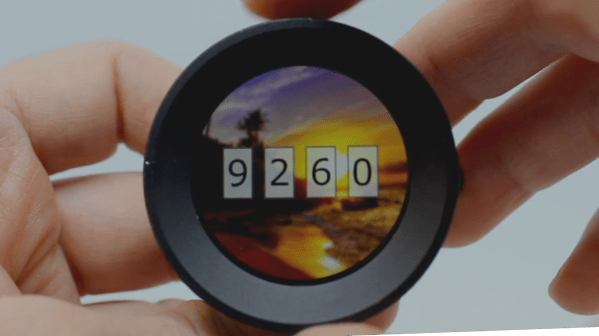
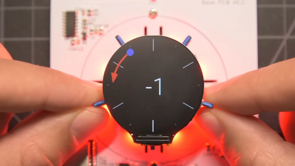
Alert readers may recall [Scott]’s announcement of this project back in March. It made quite a splash, with favorable comments and a general “Why didn’t I think of that?” vibe. And with good reason; the build quality is excellent, and the idea is simple yet powerful. By attaching a knob to the shaft of a brushless DC motor and mounting a small circular LCD screen in the middle, [Scott] came up with an input device that could be reprogrammed on the fly. The BLDC can provide virtual detents at any interval while generating haptic feedback for button pushes, and the LCD screen can provide user feedback.

But how is such a thing built? That’s the subject of the current video, which has a ton of neat design details and build insights. The big challenge for [Scott] was supporting the LCD screen in the middle of the knob while still allowing the knob — and the motor — to rotate. Part of the solution was, sadly, a hollow-shaft motor that was out of stock soon after he released this project; hopefully a suitable replacement will be available soon. Another neat feature is the way [Scott] built tiny strain gauges into the PCB itself, which pick up the knob presses that act as an input button. We also found the way button press haptics are provided by a quick jerk of the motor shaft very clever.

This is one of those projects that seems like a solution waiting for a problem, and something that you’d build just for the coolness factor. Hats off to [Scott] for following up a sweet build with equally juicy details.

Continue reading “An In-Depth Look At The Haptic Smart Knob”

Hacking A New Display Into A Fluke 8050A Multimeter

Old lab equipment was often built to last, and can give decades of service when treated properly. It’s often so loved that when one part fails, it’s considered well worth repairing rather than replacing with something newer. [Michael] did just that, putting in the work to give his Fluke 8050A multimeter a shiny new display.

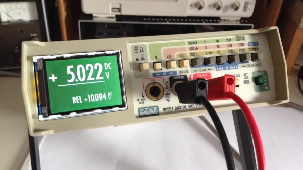
The Fluke 8050A is a versatile device, capable of measuring voltage, current, and resistance in addition to decibels at various impedences and conductance, too. The original display doesn’t show some of the finer details so well, so [Michael] elected to improve on that when he installed a new 2.2″ graphical LCD to replace the basic 7-segment LCD that originally came with the hardware.

To achieve the install, the original LCD display module was removed from the chassis. A piggyback device that sits under the Fluke’s microcontroller was then used to break out signals for the new graphical LCD without requiring modification to the meter’s PCB itself. An Atmega32u4 microcontroller then takes in these signals, and then drives the graphical LCD accordingly.

It’s a great hack that makes the old multimeter easier to use, and the new white-on-green display is far kinder on the eyes, too. We’ve seen other multimeters get screen transplants before, too. Of course, if you’re new to the world of segmented LCDs and want to learn more about how they work, [Joey Castillo]’s talk from last year’s Remoticon will get you up to speed!

Pushing The Limits Of A 16×2 LCD With Bad Apple!!

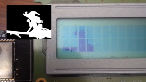
While low-contrast, blue-on-slightly-less-blue 16-character by 2-line LCDs are extremely popular, they really are made specifically for alphanumeric use. They do an admirable job of displaying a few characters, but they don’t exactly spring to mind as a display for non-character purposes. But displaying video on a 16×2 LCD is possible, as long as you’re willing to stretch the definition of “video” a bit and use some imagination while watching.

Normally, a 16×2 display can only display a single character in each spot, chosen from a fixed character set. But [arduinocelantano] was able to leverage the eight custom character slots the display allows to build up images from arbitrary 5×8 pixel bitmaps. After using ffmpeg to scale the original video to a viewport of eight characters, a Python program was used to turn every frame of the scaled video into code to generate the custom bitmaps for each chunk of the viewport. Even with the low refresh rate of the display and the shrunken frame size, the result is a recognizable video, helped no doubt by the choice of the shadow-puppet Bad Apple!! video. Check it out after the break to see how it looks.

We saw a similar rendering of the same video on LCD a while back; that effort was amazing in that it was an EEPROM-only implementation, along with a somewhat bigger LCD with better contrast. That project served as inspiration for [arduinocelantano]’s build here, which in some ways we think looks a bit better — perhaps it’s the inverted pixels. Either way, hats off to both builders for pushing past the normal constraints and teaching us something interesting.

Continue reading “Pushing The Limits Of A 16×2 LCD With Bad Apple!!

Round LCDs Put To Work In Rack Mount Gauge Cluster

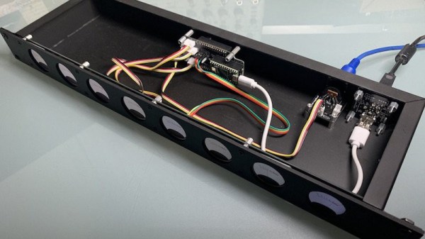
Like many of you, we’re intrigued by the possibilities offered by the availability of affordable round LCD panels. But beyond the smartwatches they were designed for, it’s not always easy to come up with an appropriate application for such non-traditional displays. Digital “steam gauges” are one of the first ideas that come to mind, so it’s perhaps no surprise that’s the direction [Tom Dowad] took his project. But rather than just one or two gauges, he decided to go all out and put eight of them in a 1U rack mountable unit.

What do you need eight faux-analog gauges for? Beats us, but that’s not our department. Now [Tom] has a whole row of indicators that can be used to show whatever it is he likes to keep an eye on. The fact that the device is actually controlled via MIDI may provide us a clue that there’s a musical component at play (no pun intended), but then, it wouldn’t be the first time we’d seen MIDI used simply as a convenient and well supported way of synchronizing gadgets. Continue reading “Round LCDs Put To Work In Rack Mount Gauge Cluster”

Monochrome LCD Video Hacks Galore!

[Wenting Zhang] is clearly a fan of old school STN LCD displays, and was wondering how various older portable devices managed to drive monochrome LCDs panels with multiple grey levels. If the display controller supports multiple bits per pixel, it can use various techniques, such as PWM, in order to produce a pseudo-grayscale image. But, what if you have a monochrome-only display controller? With a sufficiently high pixel clock, can you use software on the application side of things to flip those pixels in such a manner as to give a reasonable looking grayscale image?

Simple dithering – don’t look too close!
PDM greyscale approximation in a 1-bit display

[Wenting] goes through multiple techniques, showing the resulting image quality in a clear, systematic manner. The first idea is to use a traditional dithering technique. For each pixel, it is set to black if the grey value is below some threshold. The resulting error value, is then propagated to neighbouring pixels. This error diffusion process smears the error out over the whole display, so spatially speaking, on average the pixel values correspond roughly to the original gray values. But, the pixels themselves are still either on or off. This isn’t quite enough. The next idea is to PWM the individual pixels over multiple frames, to approximate different grey levels. But, that gives a worst case effective refresh rate of 8 Hz with a PWM period of 15 frames, at 120 fps, and that flickers. Badly. One way to mitigate that is to switch to PDM (pulse density modulation) which selects different length sequences to give the same duty cycle but at higher frequency, at least for some grey values. Slightly better, but there’s more that can be done. Continue reading “Monochrome LCD Video Hacks Galore!”

New Tech And The Old Ways

This week on Hackaday, we featured a project that tickled my nostalgia bone, and proved that there are cool opportunities when bringing new tech to old problems. Let me explain.

[Muth] shared a project with us that combines old-school analog photography printing with modern LCD screens. The basic idea is to use a 4K monochrome screen in place of a negative, making a contact print by placing the screen directly on top of photographic paper and exposing it under a uniform light source. Just like the old ways, but with an LCD instead of film.

LCD exposure animationBut what’s the main difference between a screen and film? You can change the image on the LCD at will, of course. So when [Muth] was calibrating out exposures, it dawned on him that he could create a dynamic, animated version of his image and progressively expose different portions of the paper, extending the available dynamic range and providing him the ability to control the slightest nuances of the resulting image contrast.

As an old photo geek, this is the sort of trick that we would pull off manually in the darkroom all the time. “Dodging” would lighten up a section of the image by covering up the projected light with your hand or a special tool for a part of the exposure time. With [Muth]’s procedure, he can dodge the image programmatically on the per-pixel level. We would have killed for this ability back in the day.

The larger story here is that by trying something out of the box, applying a new tool to an old procedure, [Muth] stumbled on new capabilities. As hackers, we’re playing around with the newest tech we can get our hands on all the time. When you are, it might be that you also stumble on new possibilities simply afforded by new tech. Keep your eyes open!

Stresses Revealed With A Polariscope

There are a lot of ways that stresses can show up, at least when discussing materials science. Cracks in concrete are a common enough example, but any catastrophic failure in a material is often attributable to some stress that couldn’t be withstood. If you’re interested in viewing those stresses before they result in damage to the underlying material, take a look at this DIY polariscope which can view internal stresses in glass and other clear objects.

The polariscope takes its name from the fact that it uses polarized light to view the internal structure of a transparent object such as glass. When the polarized light passes through glass in a certain way, the stresses show up as lighter areas thanks to the stressed glass bending the light back into view. This one is constructed with a polarizing filter placed in front of an LCD screen set to display a completely white image. When glass is placed between the screen and the filter no light is seen through the polariscope unless there are stresses in the glass. Even placing a force on an otherwise un-stressed glass tube can show this effect, and [Advanced Tinkering], this project’s creator, has several other creations which show this effect in striking detail.

The effect can also be observed as colored areas in other plastic materials as well. It’s an interesting tool which can help anyone who frequently works with glass, but it’s also interesting on its own to see clues left behind from the manufacturing process of various household items. We’ve seen some other investigative methods for determining how other household items are mass produced as well, like this project which breaks down the injection molding process.

Continue reading “Stresses Revealed With A Polariscope”