Power Meter

Solar Panel System Monitoring Device Using Arduino

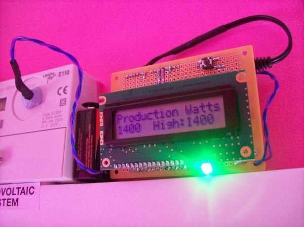
[Carl] recently upgraded his home with a solar panel system. This system compliments the electricity he gets from the grid by filling up a battery bank using free (as in beer) energy from the sun. The system came with a basic meter which really only shows the total amount of electricity the panels produce. [Carl] wanted to get more data out of his system. He managed to build his own monitor using an Arduino.

The trick of this build has to do with how the system works. The panel includes an LED light that blinks 1000 times for each kWh of electricity. [Carl] realized that if he could monitor the rate at which the LED is flashing, he could determine approximately how much energy is being generated at any given moment. We’ve seen similar projects in the past.

Like most people new to a technology, [Carl] built his project up by cobbling together other examples he found online. He started off by using a sketch that was originally designed to calculate the speed of a vehicle by measuring the time it took for the vehicle to pass between two points. [Carl] took this code and modified it to use a single photo resistor to detect the LED. He also built a sort of VU meter using several LEDs. The meter would increase and decrease proportionally to the reading on the electrical meter.

[Carl] continued improving on his system over time. He added an LCD panel so he could not only see the exact current measurement, but also the top measurement from the day. He put all of the electronics in a plastic tub and used a ribbon cable to move the LCD panel to a more convenient location. He also had his friend [Andy] clean up the Arduino code to make it easier for others to use as desired.

Nixie Inspired 7 Segment Display

The supply of Nixie tubes from east European stock piles is still enough to keep their prices down. But once those start dwindling, prices will move north. Besides, if you want to use them, you need to work with high voltage supplies and worry about not getting zapped while trying to debug a circuit. [FilleK] had some time to spare and decided to build a cheaper substitute for a real nixie tube using a regular 7 segment LED display.

We have already seen this hack before, in the Arduino-based ENIGMA replica. But [FilleK] improved on that by adding an extra LED to simulate the radiant glow typical of Nixie tubes. His project log describes the fairly straightforward process using parts that can be found easily. A piece of plastic, painted in a shade of copper and fixed around the 7 segment display, acts as a nice baffle to contain and reflect the ambient glow of the back-light LED. A nice improvement would be to add a random flicker to the background LED. Maybe add an Octal socket (the decimal point had to be nixed though!), and cap it in a proper glass tube. If you’d rather work with the real McCoy, check out our archives.

Colorful Clock

A Colorful Clock For Toddlers

[Don] and his wife were looking for a way to teach their two-year old daughter how to tell time. She understood the difference between day and night, but she wasn’t old enough to really comprehend telling the actual time. [Don’s] solution was to simplify the problem by breaking time down into colored chunks representing different tasks or activities. For example, if the clock is yellow that might indicate that it’s time to play. If it’s purple, then it’s time to clean up your room.

[Don] started with a small, battery operated $10 clock from a local retailer. The simple clock had a digital readout with some spare room inside the case for extra components. It was also heavy enough to stay put on the counter or on a shelf. Don opened up the clock and got to work with his Dremel to free up some extra space. He then added a ShiftBrite module as a back light. The ShiftBrite is a high-brightness LED module that is controllable via Serial. This allows [Don] to set the back light to any color he wants.

[Don] already had a Raspberry Pi running his DIY baby monitor, so he opted to just hijack the same device to control the ShiftBrite. [Don] started out using a Hive13 GitHub repo to control the LED, but he found that it wasn’t suitable for this project. He ended up forking the project and altering it. His alterations allow him to set specific colors and then exit the program by typing a single command into the command line.

The color of the ShiftBrite is changed according to a schedule defined in the system’s crontab. [Don] installed Minicron, which provides a nice web interface to make it more pleasant to alter the cron job’s on the system. Now [Don] can easily adjust his daughter’s schedule via web page as needed.


Flux Capacitor

Great Scott! A Flux Capacitor Notification Light

If you are into your social media, then you probably like to stay updated with your notifications. [Gamaral] feels this way but he wasn’t happy with the standard way of checking the website or waiting for his phone to alert him. He wanted something a little more flashy. Something like a flux capacitor notification light. This device won’t send his messages back in time, but it does look cool.

He started with an off-the-shelf flux capacitor USB charger. Normally this device just looks cool when charging your USB devices. [Gamaral] wanted to give himself more control of it. He started by opening up the case and replacing a single surface mount resistor. The replacement component is actually a 3.3V regulator that happens to be a similar form factor as the original resistor. This regulator can now provide steady power to the device itself, as well as a ESP8266 module.

The ESP8266 module has built-in WiFi capabilities for a low price. The board itself is also quite small, making it suitable for this project. [Gamaral] used just two GPIO pins. The first one toggles the flux circuit on and off, and the second keeps track of the current state of the circuit. To actually trigger the change, [gamaral] just connects to the module via TCP and issues a “TIME CIRCUIT ON/OFF” command. The simplicity makes the unit more versatile because an application running on a PC can actually track various social media and flash the unit accordingly.

Mapping WiFi Signals In 3 Dimensions

[Charles] is on a quest to complete ever more jaw-dropping hacks with the popular low-cost ESP8266 WiFi modules. This week’s project is plotting WiFi received signal strength in 3D space. While the ESP8266 is capable of providing a Received Signal Strength Indication (RSSI), [Charles] didn’t directly use it. He wrote a simple C program on his laptop to ping the ESP8266 at around 500Hz. The laptop would then translate the RSSI from the ping replies to a color value, which it would then send to the ESP8266. Since the ESP8266 was running [Charles’] custom firmware (as seen in his WiFi cup project), it could directly display the color on a WS2812 RGB LED.

The colors seemed random at first, but [Charles] noticed that there was a pattern. He just needed a way to visualize the LED over time. A single frame long exposure would work, but so would video. [Charles] went the video route, creating SuperLongExposure, an FFMPEG-based tool which extracts every video frame and composites them into a single frame. What he saw was pretty cool – there were definite stripes of good and bad signal.

wifiPOVThumb
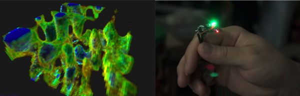
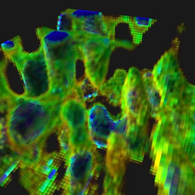
Armed with this information, [Charles] went for broke and mounted his ESP8266 on a large gantry style mill. He took several long exposure videos of a 360x360x180mm area. The videos were extracted into layers. The whole data set could then be visualized with Voxeltastic, [Charles’] own HTML5/WEBGL based render engine. The results were nothing short of amazing. The signal strength increases and decreases in nodes and anti-nodes which correspond to the 12.4 cm wavelength of a WiFi signal. The final render looks incredibly organic, which isn’t completely surprising. We’ve seen the same kind of image from commercial antenna simulation characterization systems.

Once again [Charles] has blown us away, we can’t wait to see what he does next!

Continue reading “Mapping WiFi Signals In 3 Dimensions”

Valentine Heart

Animated LED Valentine Heart

With only a week left until Valentine’s day, [Henry] needed to think on his feet. He wanted to build something for his girlfriend but with limited time, he needed to work with what he had available. After scrounging up some parts and a bit of CAD work, he ended up with a nice animated LED Valentine heart.

[Henry] had a bunch of WS2812 LEDs left over from an older project. These surface mount LED’s are very cool. They come in a small form factor and include red, green, and blue LEDs all in a single package. On top of that, they have a built-in control circuit which makes each LED individually addressable. It’s similar to the LED strips we’ve seen in the past, only now the control circuit is built right into the LED.

Starting with the LEDs, [Henry] decided to build a large animated heart. Being a stickler for details, he worked out the perfect LED placement by beginning his design with three concentric heart shapes. The hearts were plotted in Excel and were then scaled until he ended up with something he liked. This final design showed where to place each LED.

The next step was to design the PCB in Altium Designer. [Henry’s] design is two-sided with large copper planes on either side. He opted to make good use of the extra copper surface by etching a custom design into the back with his girlfriend’s name. He included a space for the ATMega48 chip which would be running the animations. Finally, he sent the design off to a fab house and managed to get it back 48 hours later.

After soldering all of the components in place, [Henry] programmed up a few animations for the LEDs. He also built a custom frame to house the PCB. The frame includes a white screen that diffuses and softens the light from the LEDs. The final product looks great and is sure to win any geek’s heart. Continue reading “Animated LED Valentine Heart”

Slick Bathroom Mirror Is All Tricked Out

A Mirror surrounded by a string of brightly lit lamps is something you usually get to see in a Movie Star’s dressing room. [pickandplace] was inspired by the Movies, and a dark bathroom, to come up with a Bathroom Mirror equipped with some bells and whistles. To start with, his planning was quite detailed, sketching out the features and constraints for his design. He chose to use a round mirror with 12 LED bulbs (which are safer than 220V bulbs) so it can work as a clock. User input is handled by a motion sensor to automatically switch it on/off and a capacitive touch dimmer. Under the hood there’s an RTC (for clock and brightness adjustment based on time of day), simple boost PWM LED driver, thermal management for the LEDs which are 10W, temperature sensor to pipe down the current if the LEDs get too hot, and even an anti-fogging heater strip – phew!

His execution is no less brilliant. Starting with building the wooden frame and ending with the code for driving all the electronics. Along the way, you will find detailed notes on the LED’s, PWM Driver, Heat sinking, and capacitive Touch dimmer using Atmel’s AT42QT2160 Qslide – Matrix Sensor IC. He had some trouble with the Motion Sensor PIR module, and hasn’t yet written the code to implement it. His first version used a PIC18F87J50, and the next iteration had an ATXmega256A3BU – but he asks us not to get into the Microchip vs. Amtel debate. We have to agree on that. Sharp readers will point out that neither of the two micro’s can provide 12 PWM channels. Well, worry not, he has it all figured out. He also coded up a simple control interface which is handy when the unit is hooked up over USB to a computer. To top it off, he built a miniature LED ring to use as a “Simulator” while working on the code so he didn’t have to lug the heavy Mirror in and out of the bathroom. How’s that for doing a good job better! Source files are on his Github repo, and links to the hardware schematics are peppered throughout his blog.

If you don’t want to build something so fancy, look up the Bathroom Mirror with HUD which displays Time and Weather

Continue reading “Slick Bathroom Mirror Is All Tricked Out”