DIY Pyrography Power Supply

Ever wanted to try your hand at wood burning? If you already threw away your first soldering iron—you know the one: plugged straight in to the wall, no temperature control, came with a thick piece of tin foil to rest it on—don’t despair. Pyrography pens don’t cost that much. The variable power supply they plug into, though: that’s another story. Those cost more than they probably should.

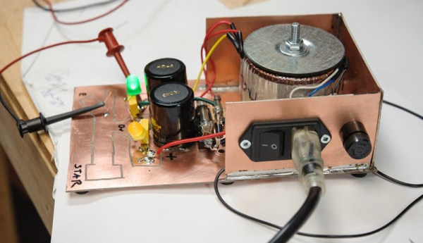
[td0g] took the plunge into pyrography a while back, and wanted to build his own controller from an old ATX power supply. Why not? It should be more than capable of doing the job. Even the most heavy-duty pyrography pens only draw 10A, and the 3.3V line showed to be rated for 30A. All [td0g] had to do was add a PWM with a MOSFET and a ‘Tiny85.

The project nearly became Fail of the Week fodder after [td0g] saw huge voltage spikes across the MOSFET. A 47kΩ resistor took care of those, and a heat sink salvaged from the junk bin will prolong the transistor’s life. [td0g] added a push button that cycles through five heat settings, and an LED to show the status. After that, all he had to do was add a male RCA input to connect the pens he already has.

Okay, so you wouldn’t be caught dead dropping money on some fancy power supply for this new hobby. Don’t want to buy pens, either? Roll your own from a plasma arc lighter.

Look What Came Out Of My USB Charger !

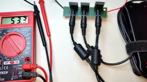
Quick Charge, Qualcomm’s power delivery over USB technology, was introduced in 2013 and has evolved over several versions offering increasing levels of power transfer. The current version — QCv3.0 — offers 18 W power at voltage levels between 3.6 V to 20 V.  Moreover, connected devices can negotiate and request any voltage between these two limits in 200 mV steps. After some tinkering, [Vincent Deconinck] succeeded in turning a Quick Charge 3.0 charger into a variable voltage power supply.

His blog post is a great introduction and walk through of the Quick Charge ecosystem. [Vincent] was motivated after reading about [Septillion] and [Hugatry]’s work on coaxing a QCv2.0 charger into a variable voltage source which could output either 5 V, 9 V or 12 V. He built upon their work and added QCv3.0 features to create a new QC3Control library.

To come to grips with what happens under the hood, he first obtained several QC2 and QC3 chargers, hooked them up to an Arduino, and ran the QC2Control library to see how they respond. There were some unexpected results; every time a 5 V handshake request was exchanged during QC mode, the chargers reset, their outputs dropped to 0 V and then settled back to a fixed 5 V output. After that, a fresh handshake was needed to revert to QC mode. Digging deeper, he learned that the Quick Charge system relies on specific control voltages being detected on the D+ and D- terminals of the USB port to determine mode and output voltage. These control voltages are generated using resistor networks connected to the microcontroller GPIO pins. After building a fresh resistor network designed to more closely produce the recommended control voltages, and then optimizing it further to use just two micro-controller pins, he was able to get it to work as expected. Armed with all of this information, he then proceeded to design the QC3Control library, available for download on GitHub.

Thanks to his new library and a dual output QC3 charger, he was able to generate the Jolly Wrencher on his Rigol, by getting the Arduino to quickly make voltage change requests.

Continue reading “Look What Came Out Of My USB Charger !”

Cleaning Up A Low-Cost Buck-Boost Supply

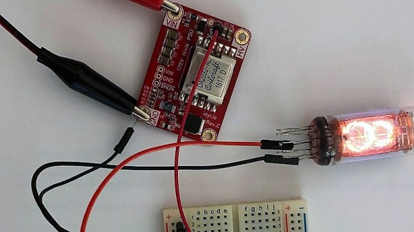
Cheap DC-DC converters have been a boon on the hobbyist bench for a while now, but they can wreak havoc with sensitive circuits if you’re not careful. The problem: noise generated by the switch-mode supply buried within them. Is there anything you can do about the noise?

As it turns out, yes there is, and [Shahriar] at The Signal Path walks us through a basic circuit to reduce noise from DC-DC converters. The module under the knife is a popular buck-boost converter with a wide input range, 0-32 VDC output at up to 5 amps, and a fancy controller with an LCD display. But putting the stock $32 supply on a scope reveals tons of harmonics across a 1 MHz band and overall ripple of about 66 mV. But a simple voltage follower built from a power op-amp and a Zener diode does a great job of reducing the spikes and halving the ripple. The circuit is just a prototype and is meant more as a proof of principle and launching point for further development, and as such it’s far from perfect. The main downside is the four-volt offset from the input voltage; there’s also a broad smear of noise at the high end of the spectrum that persists even with the circuit in place. Centered around 900 MHz as it is, we suspect a cell signal of some sort is getting in. 900 kHz.

If you haven’t checked out the videos at The Signal Path, you really should. [Shahriar] really has a knack for explaining advanced topics in RF engineering, and has a bench to die for. We’ve covered quite a few of his projects before, from salvaging a $2700 spectrum analyzer to multiplexing fiber optic transmissions.

Continue reading “Cleaning Up A Low-Cost Buck-Boost Supply”

LiPo Added To LEGO Power Functions Power Brick

LEGO’s Power Functions elements mostly consist of DC motors and the hardware to be driven by those motors like gears and wheels. They also include battery packs, usually a bunch of AA cells in a plastic box. One of the challenges of the system — for hackers, anyway — is interfacing with the product line’s plugs, which resemble 2×2 plates with power and ground connectors built in, designed to be impossible to connect in reverse. It’s difficult to make the physical shape of the plug, with the connectors right where they should be. This hurdle means you also pretty much have to use LEGO’s power boxes or take your chances with frying your components from an unregulated LiPo.

The LiPo Power Brick project serves as a DC-DC power supply, serving up constant 9 V output, with
over current protection limiting current to 3 A peak or 2 A continuous and over-discharge protection shutting down the power supply when it zeroes out. It can be used in conjunction with Sbrick smart Power Functions controllers. The SBrick can also source 3A per channel, which is more than any LEGO PF-compatible power supply can deliver.

The LiPo Power Brick is the same size as a standard 2×4 brick, allowing you to easily add it to your next project.

DPS5005 Makes Digital Power Supply A Snap

Few pieces of gear are more basic to electronics than some kind of power supply. It might be a box of batteries, or it might be a high-end lab supply. [Andreas] took a DPS5005 power supply module that has USB and Bluetooth and used it to build a very capable switching power supply which he then used to build a source measuring unit.

The user interface on the diminutive module is simplistic, so [Andreas] appreciated the PC-based software that can control the supply remotely. The module can output up to 50V, but you should plan accordingly as it does need 1.1 times the maximum voltage output on the input. It will work with lower input voltages, but it just won’t be able to output as high a voltage.

Continue reading “DPS5005 Makes Digital Power Supply A Snap”

Give Your Bench Power Supply A Helping Hand

[Sverd Industries] have created a pretty cool bench power supply integrating soldering helping hands into the build. This helps free up some much-needed bench space along with adding that wow factor and having something that looks unique.

The build is made from a custom 3D printed enclosure (Thingiverse files here), however if you have no access to a 3D printer  you could always just re-purpose or roll your own instrument enclosure. Once the enclosure is taken care of, they go on to install the electronics. These are pretty basic, using a laptop PSU with its output attached to the input of a boost/buck module. They did have to change the potentiometers from those small PCB mounted pots to full size ones of the same value though. From there they attach 4 mm banana sockets to the output along with a cheap voltmeter/ammeter LCD module. Another buck converter is attached to the laptop PSU’s output to provide 5 V for a USB socket, along with a power switch for the whole system.

Where this project really shines is the integrated helping hands. These are made from CNC cooling tubes with alligator clips super glued to the end, then heat shrink tubing is placed over the jaws to stop any accidental short circuiting while using them.

This isn’t a life changing hack but it is quite a clever idea if space is a hot commodity where you do your tinkering, plus a DIY bench power supply is almost a rite of passage for the budding hacker.

Continue reading “Give Your Bench Power Supply A Helping Hand”

Mixed Mode Bench PSU Delivers High Performance

If you have an electronics bench, it follows that you will need some form of bench power supply. While many make do with fixed-voltage supplies it’s safe to say that the most useful bench power supplies have variable voltage and a variable current limiter. These are available in a range of sizes and qualities, and can be had from the usual online suppliers starting with a surprisingly small outlay.

There is however a problem with inexpensive bench power supplies. They are invariably switch-mode designs, and their output will often be noisy. Expensive linear supplies provide a much more noise-free output, but do so at the expense of excessive heat loss when regulating a high voltage drop.

One solution is a mixed-mode design, in which a switch-mode supply does the hard work of reducing the voltage most of the way, and a linear regulator drops the last couple of volts to provide a noise-free output. [Andrei] shows us his design for just such a mixed-mode supply, and it’s one you can have a go at building yourself.

His primary supply is an off-the-shelf switcher that turns mains AC into 24 V DC. This then feeds an LTC1624 buck converter that brings the voltage down to about 1.2 V above the final output voltage, this is in turn fed to a parallel pair of LT3081 linear regulators that deliver the final noise-free output. There is an INA260 for voltage and current measurement, and an Arduino with LCD display as a user interface. His prototype has been nicely constructed using a four-layer PCB, though he suggests it could be made on stripboard with the appropriate SMD adaptors. The cardboard chassis he’s used looks slightly alarming though.

We’ve covered numerous bench power supplies here over the years here at Hackaday. If it is an author’s favourite you are seeking though, take a look at the 723.