LED cubes are really nothing new, many of us consider the building of a good sized one almost an electronics rite of passage that not so many manage to find the time or have the skill to pull off. It’s our pleasure to draw your attention to a lovely build, showing all the processes involved, the problems and the solutions found along the way.
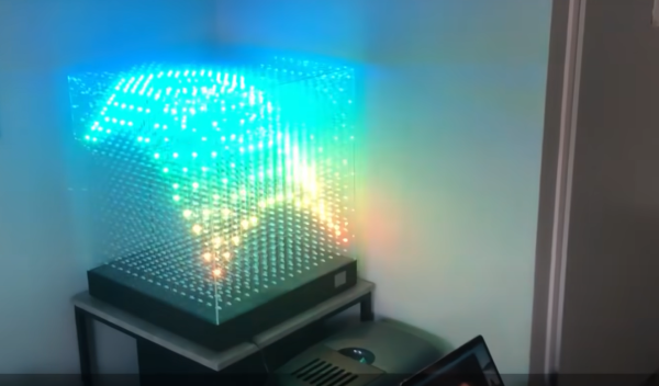
Building a small cube is somewhat of a trivial affair, especially without considering PWM colour mixing, however as simple maths will illustrate, as you increase the number of LEDs on each side, the total number will quickly get quite large. More LEDs need more power and increase control complexity considerably. A larger matrix like this 16 x 16 x 16 LED build, has a total of 4096. This would be a nightmare to drive with plain RGB LEDs, even with cunning multiplexing, but luckily you can buy indexable LEDs in a through-hole package similar to the ubiquitous WS2812-based SMT LEDs you see around. These are based on the PD9823 controller, which can be programmed as if they were a WS2812, at least according to this analysis. Now you can simply chain a column of LEDs, with the control signal passed from LED to nearest neighbour.
Early on in the video build log, you will note there are four power supply modules needed to feed this juice. If we assume each LED consumes 60 mA on full-white (the data for this product link shows a peak value of 100 mA) that is still a total of 246 A or around 1 kW of power. The video does shows a peak power measurement of around this figure, for the whole array on full white, so the maths seems about right.
Control is via a Teensy 4.0 using the FlexIO function of the IMXRT1060RM CPU, and a bunch of 74AHCT595 shift registers giving 32 channels of up to 1000 LEDs per channel if needed. Roughly speaking, using the DMA with FlexIO, the Teensy can drive up to 1 Million LED updates per second, which works out about 32 channels of 100 LEDs per channel updated at 330 frames/sec, so plenty of resource is available. All this is with almost no CPU intervention, freeing that up for handling the 2.4-inch LCD based UI and running the animations, which looks pretty darn slick if you ask us. You can checkout the description of the firmware in the firmware section of the GitHub project. 3D printed jigs allowed for bending and clipping the LEDs leads as well as fixing and aligning the LED column units, so there really is enough detail there to allow anyone so inclined reproduce this, so long as you can swallow the cost of all those LEDs.
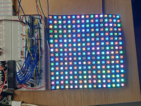
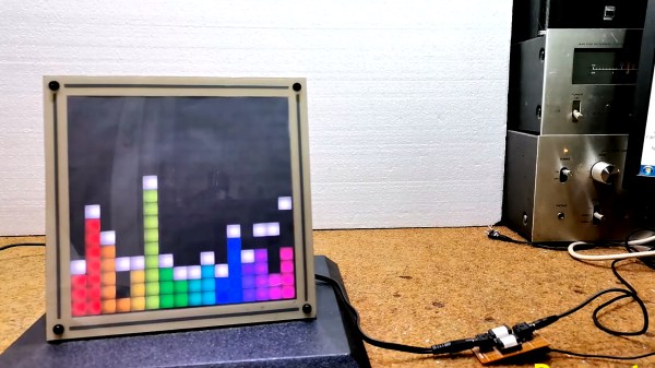
For a different approach to LED cubes, checkout this sweet panel based approach, and here’s a really small 4x4x4 module for those with less space to spare.
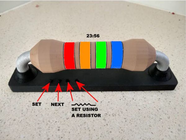
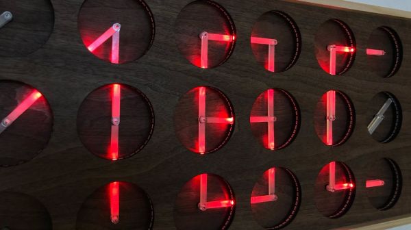
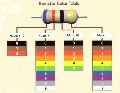 Each of the four bands represents a digit in the standard HH:MM representation of time, and for anybody well-versed in resistor codes this is sure to be a breeze to read. The clock itself was designed by [John Bradnam]. It’s body is 3D printed, with RGB LEDs to brightly illuminate each segment. The whole thing is controlled by an old favorite – an ATtiny, supported by a Real Time Clock (RTC) chip for accurate timekeeping.