DIY I2C Tester

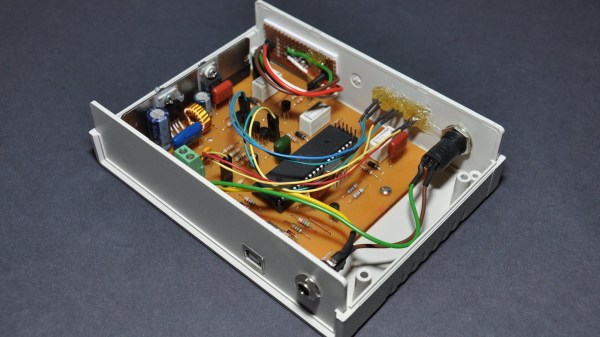
[Dilshan] built a dedicated I2C tester which allows for I2C bus control over USB using simple commands such as init, read, write, etc. The Linux kernel has had I2C driver support for a couple of decades, but you’ll be hard pressed to find a computer or laptop with a I2C connector (excluding Bunnie Huang’s Novena hacker’s laptop, of course). This tester does require a Linux host, and his programs use libusb on the computer side and V-USB on the embedded side.

[Dilshan] put a lot of time into building this project, and it shows in the build quality and thorough documentation. With its single-sided PCB and all thru-hole construction, it makes a great beginner project for someone just getting into the hobby. At the heart of the tester is an ATmega16A in a 40-pin PDIP package (despite the Microchip overview page calling it a 44-pin chip), supported by a handful of resistors and transistors. Schematics are prepared in KiCad, code is compiled using gcc and avr-gcc, and he provides a label for the enclosure top. The only thing missing is information on the enclosure itself, but we suspect you can track that down with a little sleuthing (or asking [Dilshan] himself).

If you use I2C quite a lot, give this project a look. Easy to build, useful in the lab, and it looks nice as well. We have featured [Dilshan]’s work over the years, including this logic pattern generator and his two-transistor-on-a-breadboard superheterodyne receiver.

Universal Chip Analyzer: Test Old CPUs In Seconds

Collecting old CPUs and firing them up again is all the rage these days, but how do you know if they will work? For many of these ICs, which ceased production decades ago, sorting the good stuff from the defective and counterfeit is a minefield.

Testing old chips is a challenge in itself. Even if you can find the right motherboard, the slim chances of escaping the effect of time on the components (in particular, capacitor and EEPROM degradation) make a reliable test setup hard to come by.

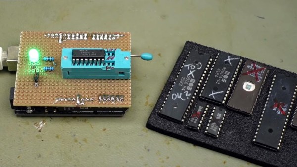
Enter [Samuel], and the Universal Chip Analyzer (UCA). Using an FPGA to emulate the motherboard, it means the experience of testing an IC takes just a matter of seconds. Why an FPGA? Microcontrollers are simply too slow to get a full speed interface to the CPU, even one from the ’80s.

So, how does it actually test? Synthesized inside the FPGA is everything the CPU needs from the motherboard to make it tick, including ROM, RAM, bus controllers, clock generation and interrupt handling. Many testing frequencies are supported (which is helpful for spotting fakes), and if connected to a computer via USB, the UCA can check power consumption, and even benchmark the chip. We can’t begin to detail the amount of thought that’s gone into the design here, from auto-detecting data bus width to the sheer amount of models supported, but you can read more technical details here.

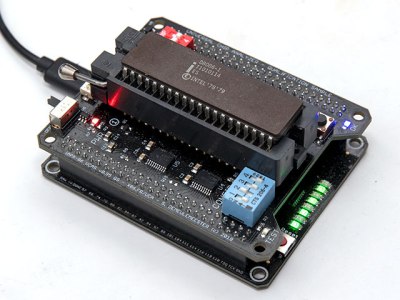
The Mojo v3 FPGA development board was chosen as the heart of the project, featuring an ATmega32U4 and Xilinx Spartan 6 FPGA. The wily among you will have already spotted a problem – the voltage levels used by early CPUs vary greatly (as high as 15V for an Intel 4004). [Samuel]’s ingenious solution to keep the cost down is a shield for each IC family – each with its own voltage converter.

Continue reading “Universal Chip Analyzer: Test Old CPUs In Seconds”

Continuity Tester Uses The ATtiny85’s Comparator

There’s an inside joke among cyclists – the number of bikes you need is “n+1”, where “n” is your current number of bikes. The same probably also applies to the number of tools and equipment a hacker needs on their workbench. Enough is never enough. Although [David Johnson-Davies] has a couple of multimeters lying around, he still felt the urge to build a stand-alone continuity tester and has posted details for a super-simple ATtiny85 based Continuity Tester on his blog. For a device this simple, he set himself some tall design goals. Using the ATtiny85 and a few SMD discretes, he built a handy tester that met all of his requirements and then some.

The ATtiny85’s Analog Comparator function is perfectly suited for such a tester. One input of the comparator is biased such that there is a 51 ohm resistor between the input and ground. The output of the comparator toggles when the resistance between the other input and ground is either higher or lower than 51 ohms. Enabling internal pullup resistors in the ATtiny85 not only takes care of proper biasing of the comparator pins, but also helps reduce current consumption when the ATtiny85 is put to sleep. The test current is limited to 100 μA, making the tester suitable for use in sensitive electronics. And enabling the sleep function after 60 seconds of inactivity reduces standby current to just about 1 μA, so there is no need for a power switch. [David] reckons the CR927 button cell ought to last pretty long.

For those interested in building this handy tester, [David] has shared the Eagle CAD files as well as the ATtiny85 code on his Github repository or you could just order out some boards from OSHpark.

MacGyvering Test Lead Clips

Okay fellow Make-Gyvers, what do you get when you cross a peripheral power cable jumper, a paperclip, springs, and some 3D-printed housings? DIY test lead clips.

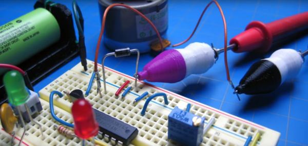
Test clips are easily acquired, but where’s the fun in that? [notionSuday] started by removing the lead connectors from the jumper, soldering them to stripped lengths of paperclip, bent tabs off the connectors to act as stoppers, and slid springs over top. Four quick prints for the housings later, the paperclip assembly fit right inside, the tips bent and clipped to work as the makeshift clamp. Once slipped onto the ends of their multimeter probes, they worked like a charm.

Continue reading “MacGyvering Test Lead Clips”

A Dual-purpose Arduino Servo Tester

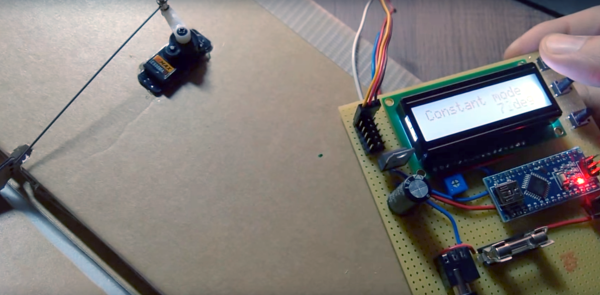
RC flying is one of those multi-disciplinary hobbies that really lets you expand your skill set. You don’t really need to know much to get started, but to get good you need to be part aeronautical engineer, part test pilot and part mechanic. But if you’re going to really go far you’ll also need to get good at electronics, which was part of the reason behind this Arduino servo tester.

[Peter Pokojny] decided to take the plunge into electronics to help him with the hobby, and he dove into the deep end. He built a servo tester and demonstrator based on an Arduino, and went the extra mile to give it a good UI and a bunch of functionality. The test program can cycle the servo under test through its full range of motion using any of a number of profiles — triangle, sine or square. The speed of the test cycle is selectable, and there’s even a mode to command the servo to a particular position manually. We’ll bet the build was quite a lesson for [Peter], and he ended up with a useful tool to boot.

Need to go even further back to basics than [Peter]? Then check out this primer on servos and this in-depth guide.

Continue reading “A Dual-purpose Arduino Servo Tester”

[Mike] Shows Us How To Use An Armature Growler

[Mike] has put up a great video  on his [SmallEngineMechanic] YouTube Channel about a tool we don’t see very often these days. He’s using an armature growler (YouTube link) to test the armature from a generator. Armature growlers (or just growlers for short) were commonplace years ago. Back when cars had generators, just about every auto mechanic had one on hand. They perform three simple tests: Check armature windings for shorts to other windings, for open windings, and for shorts to the armature body. [Mike’s] particular growler came to him as a basket case. The wiring was shot, it was rusty, and generally needed quite a bit of TLC. He restored it to like new condition, and uses it to help with his antique engine and genset addiction hobby.

Growlers essentially are a transformer primary with a V-shaped frame. The primary coil is connected to A/C mains. The armature to be tested sits in the “V” and through the magic of induction, some of the windings become the secondary coils (more on this later). This means some pretty high voltage will be exposed on commutator of the armature under test, so care should be taken when using one!

Testing for shorts to the ground or the core of the armature is a simple continuity test. Instead of a piezo beep though, a short will trigger the growler to turn on, which means the armature will jump a bit and everything will emit a loud A/C hum. It certainly makes testing more interesting!

Checking for open windings is a matter of energizing the growler’s coil, then probing pairs of contacts on the commutator.  Voltage induced in the windings is displayed on the growler’s meter. Open windings will show 0 volts. Not all the armature’s windings will be in the field of the growler at once – so fully testing the armature will mean rotating it several times, as [Mike] shows in his video.

The final test is for shorted coils. This is where things get pretty darn cool. The growler is switched on and a thin piece of ferrous metal – usually an old hacksaw blade, is run along the core of the armature. If a short exists, the hacksaw blade will vibrate against the core of the armature above the shorted windings. We’re not 100% clear on how the coupling between the growler’s primary and two windings causes the blade to vibrate, so feel free to chime in over in the comments to explain things.

Most commercial shops don’t troubleshoot armatures anymore, they just slap new parts in until everything works again. As such the growler isn’t as popular as it once was. Still, if you work with DC motors or generators, it’s a great tool to have around, and it’s operation is a pretty darn cool hack in itself.

Click past the break for [Mike’s] video!

Continue reading “[Mike] Shows Us How To Use An Armature Growler”

Hackaday Links: July 13, 2012

Testing LEDs

Over at the Albuquerque, NM hackerspace Quelab, [Alfred] needed to test a bunch of surface mount LEDs. He ended up building a pair of 3D printed tweezers with a pair of needles attached to the end and a space for a coin cell battery. It works and Quelab got a new tool.

Woo Raspberry Pi

[tech2077] added an FTDI chip to his Raspberry Pi to do a little single cable development. We’ve seen a few similar builds, but surprisingly nothing related to the on board display serial interface. This wiki page suggests it’s possible to connect an iPhone 3G or iPhone 4 display directly to the Raspi. Does anyone want to try that out?  Nevermind, but it would be cool to get a picture from a display plugged into that display port on the Raspi.

I like to ride my bicycle, I like to ride my bike

Over at the 23b hackerspace a few people were having trouble finding a good bike cargo rack that wasn’t overpriced. They built their own with $30 in materials and a salvaged milk crate. It looks great and is most likely a lot more durable than the Walmart model.

If that cargo rack fell off, it would look like this

Apparently you can get ‘spark cartridges’ to attach to the underside of a skateboard. [Jim] saw these would look really cool attached to his bike so he did the next best thing. He attached them to his sandals. It does look cool…

Less heat, less noise

[YO2LDK] picked up a TV tuner dongle for software radio and found it overheated and stopped working after about 15 minutes (Romanian, Google Translate). He hacked up a heat sink from an old video card to solve this problem. Bonus: the noise was reduced by a few tenths of a dB.