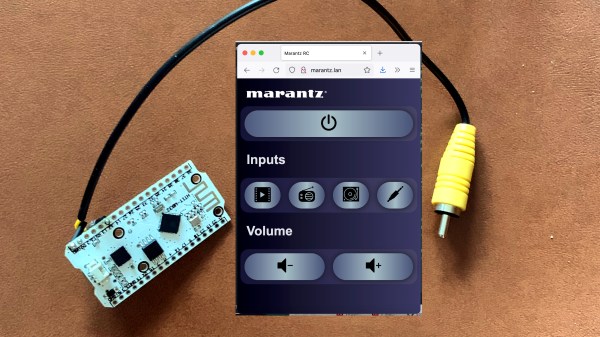
[Alex] recently gave a Marantz audio amplifier the ability to be remotely-controlled via WiFi by interfacing an ESP32 board to a handy port, but the process highlights how interfacing to existing hardware often runs into little, unforeseeable problems that can sink the project unless solved.
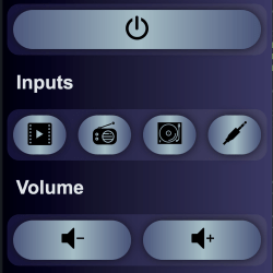 At its core, the project uses an ESP32 and the ESPAsyncWebServer project to create a handy web interface that is accessible over WiFi. Then, to actually control the amplifier, [Alex] decoded the IR-based remote signals by watching the unit’s REMOTE ports, which are intended as a pass-through and repeater for IR signals to other Marantz units. This functionality can be exploited; by sending the right signals to the REMOTE IN port, the unit can be controlled by the ESP32. With the ESP32 itself accessible by just about any WiFi device, [Alex] gains the freedom to control his amplifier with much greater flexibility than just the IR remote would offer.
Sounds fairly straightforward, but as usual when interfacing to an existing piece of electronics, there were a few glitches. The first was that high and inconsistent latency (from 10 ms to 100 ms) made controlling the amplifier a sometimes frustrating experience, but that was solved by disabling power saving on the WiFi interface. Another issue was that sending signals by connecting a GPIO pin to the REMOTE IN port of the amplifier worked, but had the side effect of causing the amplifier to no longer listen to the IR remote. Apparently, current flowing from the REMOTE port to the ESP32’s GPIO pin was to blame, because adding a diode in between fixed the problem.
The GitHub repository holds the design files and code. This kind of project can be pretty complex, because the existing hardware doesn’t always play nice, and useful boards like a modern ESP32 aren’t always available. Adding a wireless interface to vintage audio equipment has in the past involved etching circuit boards and considerably more parts.

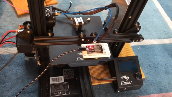
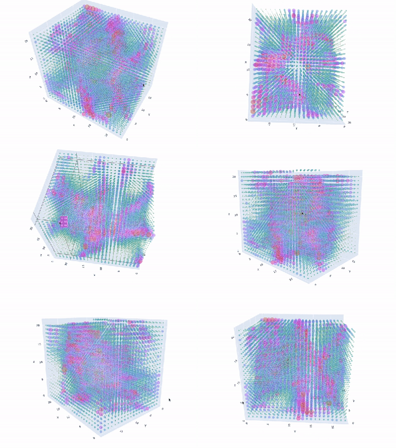 Granted, based as it is on the gantry of an old 3D printer, [Neumi]’s WiFi scanner has a somewhat limited work envelope. A NodeMCU ESP32 module rides where the printer’s extruder normally resides, and scans through a series of points one centimeter apart. A received signal strength indicator (RSSI) reading is taken from the NodeMCU’s WiFi at each point, and the position and RSSI data for each point are saved to a CSV file. A couple of Python programs then digest the raw data to produce both 2D and 3D scans. The 3D scans are the most revealing — you can actually see a 12.5-cm spacing of signal strength, which corresponds to the wavelength of 2.4-GHz WiFi. The video below shows the data capture process and some of the visualizations.