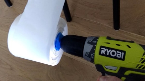
Toilet paper has become a hot button issue over the last month or so, and the pandemic prompted panic buying, and consequent shortages. Now there are adequate supplies, at least where this is being written, but sometimes one’s rolls aren’t the domestic items we’re all used to. This happened to [Ebenezer], who had some of the large size rolls suitable for toilet roll dispensers rather than a domestic bathroom. To solve this problem he made a makeshift toilet roll winder.
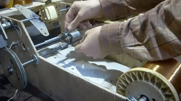
The adventures of small dogs aside, we all know that toilet rolls unroll themselves very easily indeed but are a significant pain to get back on the roll once they have done so. Rolling toilet paper must therefore be an exact science of velocity and tension, which he approached with a 3D printed shaft that mounts a toilet roll tube in a Ryobi drill. Getting the tension right was a bit tricky, but we’re extremely impressed with the result. Like him we’d have expected some side-to-side movement, but there was very little and a near perfect toilet roll was the result.
This is a simple hack, but one extremely well executed, and that it does something we might normally consider near-impossible is a bonus. Of course, should you wish to ration your toilet paper, you can always print it.