Building A Semiautomatic Swag Launcher

Regular readers of Hackaday have certainly seen the work of [Jeremy Cook] at this point. Whether you remember him from his time as a writer for this fine online publication, or recognize the name from one of his impressive builds over the last few years, he’s a bona fide celebrity around these parts. In fact, he’s so mobbed with fans at events that he’s been forced to employ a robotic companion to handle distributing his personalized buttons for his own safety.

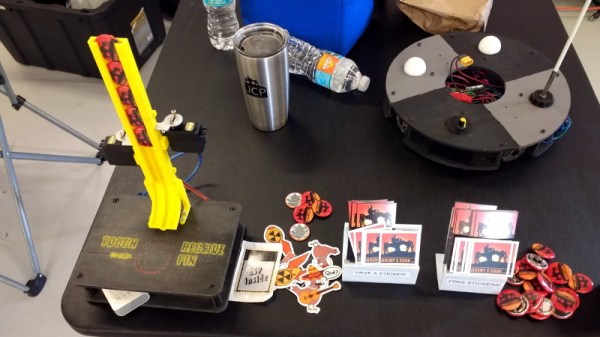
Alright, that might be something of a stretch. But [Jeremy] figured it couldn’t hurt to have an interesting piece of hardware handing out his swag at the recent Palm Bay Mini Maker Faire. Anyone can just put some stickers and buttons in a bowl on a table, but that’s hardly the hacker way. In the video after the break, he walks viewers through the design and construction of this fun gadget, which takes a couple unexpected turns and has contains more than a few useful tips which are worth the cost of admission alone.

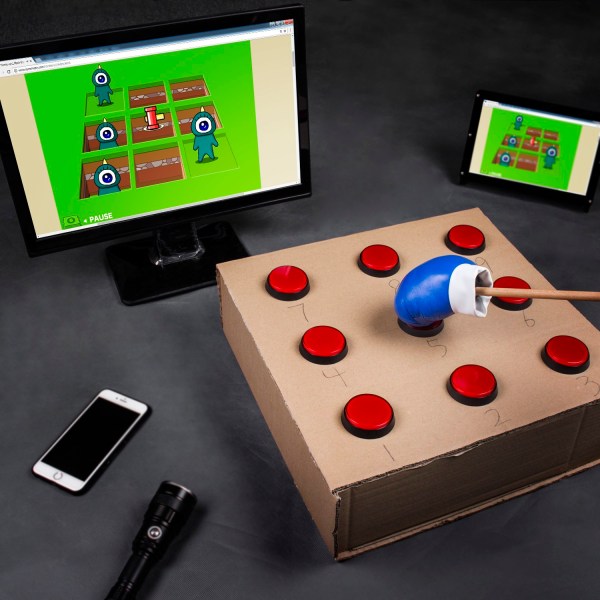
Outwardly the 3D printed design is simple enough, and reminds us of those track kits for Matchbox cars. As you might expect, getting the buttons to slide down a printed track was easy enough. Especially when [Jeremy] filed the inside smooth to really get them moving. But the goal was to have a single button get dispensed each time the device was triggered, but that ended up being easier said than done.

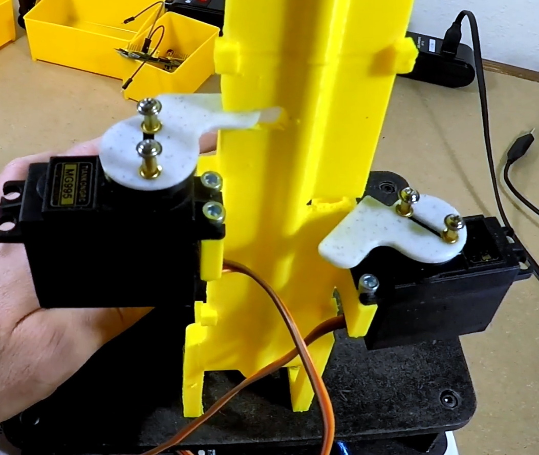
The first attempt used magnets actuated by two servos, one to drop the button and the other to hold up the ones queued above it. This worked fine…at first. But [Jeremy] eventually found that as he stacked more buttons up in the track, the magnets weren’t strong enough to hold them back and they started “leaking”. This is an excellent example of how a system can work perfectly during initial testing, but break down once it hits the real world.

In this case, the solution ended up being relatively simple. [Jeremy] kept the two servos controlled by an Arduino and a capacitive sensor, but replaced the magnets with physical levers. The principle is the same, but now the system is strong enough to hold back the combined weight of the buttons in the chute. It did require him to cut into the track after it had already been assembled, but we can’t blame him for not wanting to start over.

Just like the arcade inspired candy dispenser, coming up with a unique way of handing out objects to passerby is an excellent way to turn the ordinary into a memorable event. Maybe for the next iteration he can make it so getting a button requires you to pass a hacker trivia test. Really make them work for it.

Continue reading “Building A Semiautomatic Swag Launcher”

What’s The Cheapest Way To Scan Lots Of Buttons?

So you’re building a new mechanical keyboard. Or attaching a few buttons to a Raspberry Pi. Or making the biggest MIDI grid controller the world has ever know. Great! The first and most important engineering question is; how do you read all those buttons? A few buttons on a ‘Pi can probably be directly connected, one for one, to GPIO pins. A mechanical keyboard is going to require a few more pins and probably some sort of matrix scanner. But the grid controller is less clear. Maybe external I/O expanders or a even bigger matrix? Does it still need diodes at each button? To help answer these questions the folks at [openmusiclabs] generated a frankly astounding map which shows, given the number of inputs to scan and pins available, which topology makes sense and roughly how much might it cost. And to top it off they link into very readable descriptions of how each might be accomplished. The data may have been gathered in 2011 but none of the fundamentals here have changed.

How do you read this chart? The X axis is the number of free pins on your controller and the Y is the number of I/Os to scan. So looking at the yellow band across the top, if you need to scan one input it always makes the most sense to directly use a single pin (pretty intuitive, right?). Scrolling down, if you need to read 110 inputs but the micro only has eight pins free there are a couple choices, keys E and F. Checking the legend at the top E is “Parallel out shift register muxed with uC” and F is “Parallel in shift register muxed with uC“. What do those mean? Checking the table in the original post or following the link takes us to a handy descriptive page. It looks like a “parallel out shift register” refers to using a shift register to drive one side of the scan matrix, and “parallel in shift register” refers to the opposite.

Continue reading “What’s The Cheapest Way To Scan Lots Of Buttons?”

DIY Switches For People Who Can’t Push Switches

An outstanding number of things most people take for granted present enormous hurdles for people with physical disabilities, including interaction with computers and other digital resources. Assistive technologies such as adaptive switches allow users who cannot use conventional buttons or other input devices to interact with digital devices, and while there are commercial offerings there is still plenty of room for projects like [Cassio Batista]’s DIY Low-cost Assistive Technology Switches.

[Cassio]’s project focuses on non-contact switches, such as proximity and puff-based activations. These are economical, DIY options aimed at improving accessibility for people who are unable to physically push even specialized switches. There are existing products in this space, but cost can be a barrier and DIY options that use familiar interfaces greatly improves accessibility.

Assistive technologies that give people the tools they need to have more control over their own lives in a positive, healthy way is one of the more vibrant and positive areas of open hardware development, and it’s not always clear where the challenges lie when creating solutions. An example of this is the winner of the 2015 Hackaday Prize, the Eyedrivomatic, which allows one to interface the steering of an electric wheelchair to a gaze tracking system while permanently altering neither device; a necessity because users often do not own their hardware.

Print Physical Buttons For Your Touch Screen

Modern handheld gaming hardware is great. The units are ergonomic powerhouses, yet many of us do all our portable gaming on a painfully rectangular smartphone. Their primary method of interaction is the index finger or thumbs, not a D-pad and buttons. Shoulder triggers have only existed on a few phones. Bluetooth gaming pads are affordable but they are either bulky or you have to find another way to hold your phone. Detachable shoulder buttons are a perfect compromise since they can fit in a coin purse and they’re cheap because you can make your own.

[ASCAS] explains how his levers work to translate a physical lever press into a capacitive touch response. The basic premise is that the contact point is always touching the screen, but until you pull the lever, which is covered in aluminum tape, the screen won’t sense anything there. It’s pretty clever, and the whole kit can be built with consumables usually stocked in hardware stores and hacker basements and it should work on any capacitive touch screen.

Physical buttons and phones don’t have to be estranged and full-fledged keyswitches aren’t exempt. Or maybe many capacitive touch switches are your forte.

Continue reading “Print Physical Buttons For Your Touch Screen”

Hack Together A Whack-A-Mole In A Box!

Here’s a project that you can throw together in an afternoon, provided you have the parts on hand, and is certain to entertain. Hackaday.io user [SunFounder] walks us through the process of transforming a humble cardboard box into a whack-a-mole game might be just the ticket to pound out some stress or captivate any children in the vicinity.

A multi-control board and nine arcade buttons are the critical pieces of hardware here, with wires and a USB cable rounding out  the rest of the electronics. Separate the button core from the upper shell, mounting the shell in the box, and connect the button core’s LED cathode to the button’s ON terminal. Repeat eight times. Solder the buttons in parallel and add some more wire to the buttons’ ON terminals to extend their reach. Repeat eight more times.

Place the finished LED+cores into the buttons and connect their ON terminals to their respective buttons on the multi control board. Now for the hard step: use a mini-USB to USB cable to connect the controller to a computer you want to use to run the game’s code in the Arduino IDE. Modify the key-mappings and away you go! Check out the build video after the break.

Continue reading “Hack Together A Whack-A-Mole In A Box!”

Softly To Sleep, My Raspberry Pi

For all their capacity, shutting down a Raspberry Pi can be a bothersome routine depending on how you have it set up — historically and abrupt cut to the power risks corrupting the SD card. [madlab5] had to make a few changes to a Pi running in headless mode, requiring them to access it externally to shut it down to prevent any damage from pulling the plug. So, why not take the opportunity to whip up a soft shut-down switch?

This is a great beginner project to get one accustomed to working with a Pi. With this in mind, [madlab5] went through two revisions of this idea: the simple way, and the fun way. For the simple way just press the button and the Pi activates a script which shuts it down in thirty seconds. Job done. But, realizing there may be a few circumstances where they’d need more functionality, [madlab5] decided to take a second swing at this.

[madlab5]’s fun way involves a button with a built-in LED and a speaker to blare an announcement that the Pi will self destruct shut down after a short time. Setting the switch up this way takes a little more doing, but you get to add a little more character to your Pi with a custom shutdown report, as well as the option to cancel an accidental button-press.

For any newbies out there, [madlab5] is kind enough to provide their code and diagrams in their blog post. If remotes are more your thing, we have also featured a similar beginner project to shut down your Pi.

[via /r/Raspberry_Pi_Projects]

Fidget Pyramid With Help From A 2500 Pound Robot

Depending on whom you ask, fidgeting is an unsightly habit or a necessity for free-form ideation. Fan of the latter hypothesis? Well, why aren’t you making yourself a fidget pyramid?

[lignum] sculpted his fidget toy out of a chunk of 2000 year old bog-oak using hand tools and a little precision help from a Kuka KR 150 industrial robot arm. A push button, a toggle switch, a ball-bearing, and a smooth side provide mindless distraction on this piece.

Two plates of 1.5mm aluminium — also cut using the robot arm — are used to attach the button and toggle to the tetrahedron, while the ball bearing is pushed onto a cylindrical protrusion left during the cutting process for the purpose. The build video makes it look easy.

Continue reading “Fidget Pyramid With Help From A 2500 Pound Robot”