As convenient as cell phones are, sometimes these power-hungry devices let us down right at the worst time. We’re talking about battery life and how short it is in modern cell phones. Sure that’s totally inconvenient sometimes but it could be way worse. For example: during a natural disaster. A cyclone hit [Ganesh’s] home city and the entire area had lost power for 10 days. He couldn’t plug in his phone to charge it even if he wanted to. After realizing how dependent we are on the electrical grid, he did something about and built a phone charger out of parts he had kicking around.
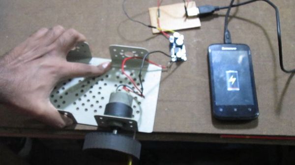
The charger is quite simple. The user cranks on a DC motor and the output power goes into a LM2596-based step-down voltage regulator. The output of the regulator is then connected to a female USB connector so that any USB cord can be plugged in. As long as the motor is cranked fast enough to put out at least 8vdc, a steady stream of 5v will be available at the USB connector. Max current output of the system has been measured at 550mA.
[Ganesh] admits this isn’t a practical every-day charger but in a pinch it will certainly do the trick. It is even possible to build a makeshift charger out of a cordless drill.
Continue reading “DIY Phone Charger Born From Cyclone Disaster”


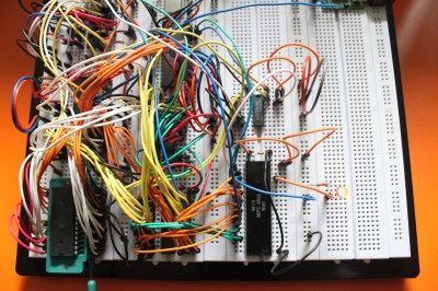 [Dirk] has some great documentation to go with his computer. He started with a classic MOS 6502 processor. He surrounded the processor with a number of support chips correct for the early 80’s period. RAM is easy-to -use static RAM, while ROM is handled by UV erasable EPROM. A pair of MOS 6522 Versatile Interface Adapter (VIA) chips connect the keyboard, LCD, and any other peripherals to the CPU. Sound is of course provided by the 6581 SID chip. All this made for a heck of a lot of wires when built up on a breadboard. The only thing missing from this build is a way to store software written on the machine. [Dirk] already is looking into ways to add an SD card interface to the machine.
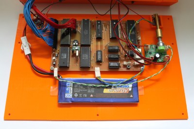 The home building didn’t stop there though. [Dirk] designed and etched his own printed circuit board (PCB) for his computer. DIY PCBs with surface mount components are easy these days, but things are a heck of a lot harder with older through hole components. Every through hole pin and via had to be drilled, and soldered to the top and bottom layers of the board. Not to mention the fact that both layers had to line up perfectly to avoid missing holes! To say this was a lot of work would be an understatement.
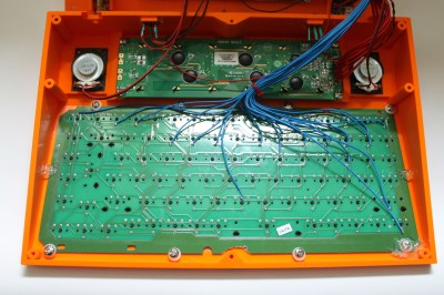 [Dirk] designed a custom 3D printed case for his computer and printed it out on his Ultimaker. To make things fit, he created his design in halves, and glued the case once printing was complete.
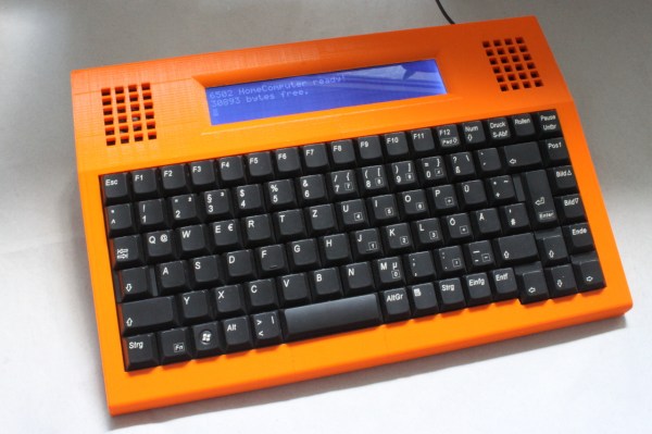