Touch-A-Sketch Gives An Old Toy A New Twist

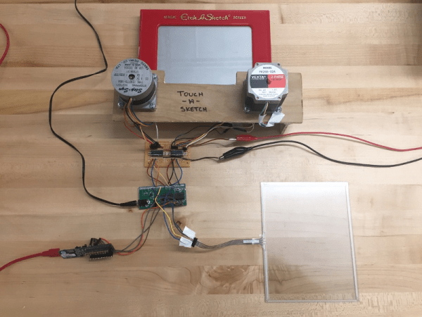
After nearly 60 years and a lot of stairs and squares, there is finally an easier way to draw on an Etch A Sketch®. For their final project in embedded microcontroller class, [Serena, Francis, and Alejandro] implemented a motor-driven solution that takes input from a touch screen.

Curves are a breeze to draw with a stylus instead of joysticks, but it’s still a 2-D plotter and must be treated as such. The Touch-A-Sketch system relies on the toy’s stylus starting in the lower left hand corner, so all masterpieces must begin at (0,0) on the knobs and the touch screen.

The BOM for this project is minimal. A PIC32 collects the input coordinates from the touch screen and sends them to a pair of stepper motors attached to the toy’s knobs. Each motor is driven by a Darlington array that quickly required a homemade heat sink, so there’s even a hack within the hack. The team was unable to source couplers that could deal with the discrepancy between the motor and knob shaft sizes, so they ended up mounting the motors in a small plywood table and attaching them to the stock knobs with Velcro. This worked out for the better, since the Etch A Sketch® screen still has to be reset the old-fashioned way.

They also considered using belts to drive the knobs like this clock we saw a few years ago, but they wanted to circumvent slippage. Pour another glass of your aunt’s high-octane eggnog and watch Touch-A-Sketch draw something festive after the break.

Continue reading “Touch-A-Sketch Gives An Old Toy A New Twist”

There Once Was An IC Dedicated To Blinking An LED

Today you can buy flashing LEDs; a simple two-lead component that requires only a power supply to produce even flashes of light. They look for all the world like any other LED, though embedded in the plastic dome is an integrated circuit to do all that flashing work.

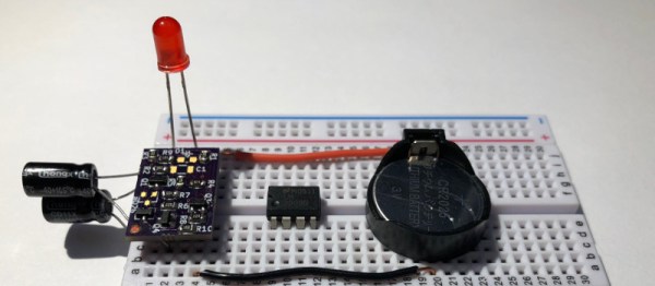
There was a time though when a flashing LED was something of a big deal, so much so that National Semiconductor produced a dedicated chip for the task. The LM3909 boasted the ability to flash an LED for over a year using a single C battery. That part is now long out of production, so [Dillon] has implemented the LM3909 circuit using discrete components on a small PCB designed to take pins and fit the footprint of the original.

Why on earth might a reborn LM3909 be of interest to him, you ask? Well, he wasn’t able to make a 555 flash the LED from a coin cell, and a friend mentioned this chip which piqued his interest. The internal schematic is in the data sheet (found in the files section of his project), so he was able to implement it relatively easily using common parts. It still requires an external capacitor just like the original, but there is space on-board should you wish to put it there.

He’s produced a video we’ve placed below the break showing the device in action, proving it to be a drop-in replacement for an original. Recreations of classic chips using discretes are nothing new, we recently brought you a reborn PSU regulator chip made in 2014. An while you’re playing around with coin cell batteries, may we direct your attention to the Coin Cell Challenge.

Continue reading “There Once Was An IC Dedicated To Blinking An LED”

Guide: Why Etch A PCB When You Can Mill?

I recall the point I started taking electronics seriously, although excited, a sense of dread followed upon the thought of facing the two main obstacles faced by hobbyists and even professionals: Fabricating you own PCB’s and fiddling with the ever decreasing surface mount footprints. Any resistance to the latter proves futile, expensive, and frankly a bit silly in retrospect. Cheap SMD tools have made it extremely easy to store, place, and solder all things SMD.

Once you’ve restricted all your hobbyist designs/experiments to SMD, how do you go about producing the PCBs needed for prototyping? Personally, I dread the thought of etching my own boards. The process is laborious and involves messy chemicals and specially sensitized PCB’s — none of which interest me. I’ve only ever done it a few times, and have promised myself never to do it again. Professional but cheap PCB manufacturing is more like it board pooling services such as OSH park have made this both easy and affordable — if you can wait for the turnaround.

So what are the alternatives? If you are really serious about swift prototyping from your own Lab, I put forth the case of milling your own PCB’s. Read on as I take you through the typical workflow from design to prototype and convince you to put up with the relatively high start up cost of purchasing a PCB mill.

Continue reading “Guide: Why Etch A PCB When You Can Mill?”

Huge 3D Printer Ditches Lead Screw For Belt Driven Z Axis

The vast majority of desktop 3D printers in use today use one or more lead screws for the Z-axis. Sometimes you need to think outside of the box to make an improvement on something. Sometimes you need to go against the grain and do something that others wouldn’t do before you can see what good will come out of it. [Mark Rehorst] had heard the arguments against using a belt drive for the Z-axis on a 3D printer build:

  1. The belt can stretch, causing inaccurate layer height.
  2. If power fails, gravity will totally ruin your day.

He decided to go for it anyway and made a belt driven Z axis for his huge printer. To deal with the power loss issue, he’s using a 30:1 reduction worm gear on the drive — keeping the bed in one place if power goes. And after a few studies, he found the belt stretch was so minimal that it has no effect on layer height.

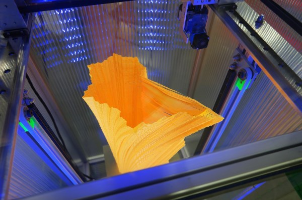
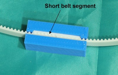
Of course those two issues are but a small portion of the overall ingenuity that [Mark] poured into this project. You’ll want to see it in action below, printing a vase that is 500 mm tall (took about 32 hours to get to 466 mm and you can see the top is a hairy wobbly at this point). Luckily we can geek out with the rest of his design considerations and test by walking through this fantastic build log from back in July. Of note is the clamp he designed to hold the belt. It uses a small scrap of the belt itself to lock together the two ends. That’s a neat trick!

The introduction of a belt driven Z-axis eliminates Z-axis wobble — an issue that can be exacerbated in tall printers. Desktop 3D printers are constantly improving, and we’re always excited to see a new trick work so well. Let us know if you’ve seen any other handy Z-axis modifications out there.

Continue reading “Huge 3D Printer Ditches Lead Screw For Belt Driven Z Axis”

Repairing A Macbook Charger… With A Pistachio Nut

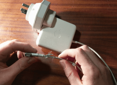
Laptop chargers face a hard life. They’re repeatedly plugged and unplugged, coiled up, stuffed into bags, thrown around, and just generally treated fairly poorly. Combine this with fairly lightweight design and it’s not uncommon for a laptop charger to fail after a few years. It’s usually the connector that goes first. Such was the case when I found myself face to face with a failed Macbook charger, and figured it’d be a simple fix. Alas, I was wrong.

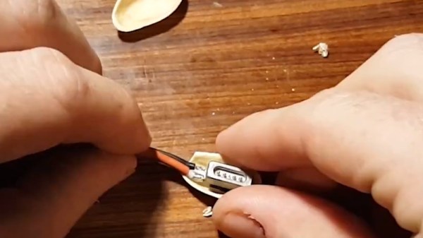
Unlike most PC manufacturers, who rely on the humble barrel jack and its readily available variants, Apple liked to use the Magsafe connector on its Macbook line. This connector has many benefits, such as quick release in the event someone trips over the cable, and the fact that it can be plugged in without regard to orientation. However, it’s not the easiest to fix. When the charger began failing, I noticed two symptoms. The first was that the charger would only function if the cable was held just so, in exactly the right orientation. The other, was that even when it would charge, the connector would become very hot. This led me to suspect an intermittent connection was the culprit, and it was quite a poor one at that; the high resistance leading to the heat issue.

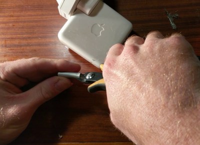
It’s at this point with any other charger that you get out your trusty sidecutters, lop the end off, and tap away at Digikey to get a replacement part on the way. With Magsafe? No dice. Replacement parts simply aren’t available — a common problem with proprietary connectors. I endeavoured to fix the problem anyway. I began to strip away the metal shell around the back of the connector with my sidecutters, and eventually an angle grinder. A Dremel would have been the perfect tool for the job, actually, but I persevered regardless. After much consternation, I had the connector peeled back and was able to identify the problem.

Continue reading “Repairing A Macbook Charger… With A Pistachio Nut”

Making Solar Cells

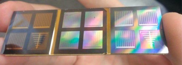
We will admit that it is unlikely you have enough gear in your basement to make a solar cell using these steps. However, it is interesting to see how a bare silicon wafer becomes a solar cell. If you’ve seen ICs going through fabrication, you’ll see a lot of similarities, but there are some differences.

The process calls for a silicon wafer, some ovens, spin coaters, photolithography equipment, and a dice saw, among other things. Oh, you probably also need a clean room. Maybe you should just buy your solar cells off the shelf, but it is still interesting to see how they are made.

Modern solar cells have some extra structures to improve their efficiency, but the cells in this video are pretty garden-variety. For example, some experimental cells use multiple layers of active devices, each tuned to absorb a different wavelength of light.

If you really want to make your own, there’s another process where you can start with some copper and wind up with a kind of solar cell that uses a copper-based semiconductor material. But don’t be fooled into thinking that making the silicon variety is totally out of reach to hackers, we’ve seen [Sam Zeloof] pull it off.

Continue reading “Making Solar Cells”

Two Factor Authentication With The ESP8266

Google Authenticator is a particularly popular smartphone application that can be used as a token for many two factor authentication (2FA) systems by generating a time-based one time password (referred to as TOTP). With Google Authenticator, the combination of your user name and password along with the single-use code generated by the application allows you to securely authenticate yourself in a way that would be difficult for an attacker to replicate.

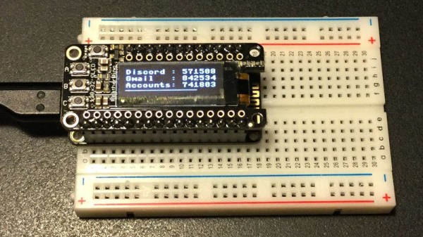
That sounds great, but what if you don’t have a smartphone? That’s the situation that [Lady Ada] recently found herself in, and rather than going the easy route and buying a hardware 2FA token that’s compatible with Google Authenticator, she decided to build one herself based on the ESP8266. With the hardware and source documented on her site, the makings of an open source Google Authenticator hardware token are available for anyone who’s interested.

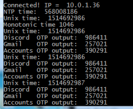
Generated codes can also be viewed via serial.

For the hardware, all you need is the ESP8266 and a display. Naturally [Lady Ada] uses her own particular spin on both devices which you can purchase if you want to create an identical device, but the concept will work the same on the generic hardware you’ve probably already got in the parts bin. Software wise, the code is written in CircuitPython, a derivative of MicroPython, which aims to make microcontroller development easier. If you haven’t tried MicroPython before, grab an ESP and give this a roll.

Conceptually, TOTP is relatively simple. You just need to know what time it is, and run an SHA1 hash. The time part is simple enough, as the ESP8266 can connect to the network and get the current time from NTP. The calculation of the TOTP is handled by the Python code once you’ve provided it with the “secret” pulled from the Google Authenticator application. It’s worth noting here that this means your 2FA secrets will be held in clear-text on the ESP8266’s flash, so try not to use this to secure any nuclear launch systems or anything, OK? Then again, if you ever lose it the beauty of 2-factor is you can invalidate the secret and generate a new one.

We’ve covered the ins and outs of 2FA applications before here at Hackaday if you’d like to know more about the concept, in addition to previous efforts to develop a hardware token for Google Authenticator.