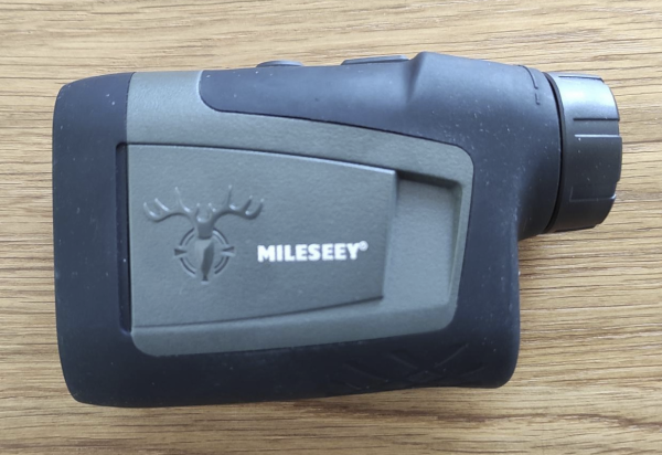
Motorcycle Rally Computer Goes Open Source

Motorcycle rally racing is a high-speed, exciting, off-road motorsport that involves zipping across all types of terrain on two wheels. While riding, it’s extremely important for riders to know what’s coming up next —  turns, straightaways, stream crossings, the list goes on. Generally, this is handled by a roadbook — a paper scroll that has diagrams of each turn or course checkpoint, along with the distances between them and any other pertinent information. Of course, this needs to be paired with a readout that tells you how far you’ve traveled since the last waypoint so you’re not just guessing. This readout usually takes the form of a rally computer, a device that can display speed, distance traveled, and course heading (and some of the fancier ones have even more data available).

A roadbook with commercially-available rally computers

Frustrated with the lackluster interface and high cost associated with most rally computers on the market, [Matias Godoy] designed his own back in 2017, and was quick to realize he had a potential product. After several iterations he brought his idea to market with a small initial run, which sold out in a few hours!

He then took some time to reflect on the successful campaign. He decided that rather than continue to churn out units, he would open-source the design to make it available to everybody and see what the community could come up with. He published all of his design files to GitHub, and wrote up a wonderful blog post documenting the entire design process, from inspiration and early prototypes to his decision to go open source.

[Matias]’s project, the Open Rally Computer (formerly the Baja Pro) packages neatly in a CNC-machined case and features a nice high-visibility LCD display, a built-in GPS receiver, and an ergonomic handlebar-mounted remote. The data is crunched by an ESP32 microcontroller, which also allows for WiFi-enabled OTA updates. The end result is a beautiful and useful device that was clearly designed with great care. Love the idea but not a rally racer? If street bikes are more your thing then fear not because there’s an open source digital dashboard out there for you too.

3D Printed Absolute Encoder Is Absolutely Wonderful

When you need to record the angle of something rotating, whether it’s a knob or a joint in a robotic arm, absolute rotary encoders are almost always the way to go. They’re cheap, they’re readily available, and it turns out you can make a pretty fantastic one out of a magnetic sensor, a zip tie, and a skateboard bearing.

When [Scott Bezek] got his hands on a AS5600 magnet sensor breakout board, that’s just what he did. The sensor itself is an IC situated in the middle of the board, which in Scott’s design sits on a 3D-printed carrier. A bearing mount sits atop it, which holds — you guessed it — a bearing. Specifically a standard 608 skateboard bearing, which is snapped into the mount and held securely by a zip tie cinched around the mount’s tabs. The final part is a 3D-printed knob with a tiny magnet embedded within, perpendicular to the axis of rotation. The knob slides into the bearing and the AS5600 reads the orientation of the magnet.

Of course, if you just wanted a rotary knob you could have just purchased an encoder and been done with it, but this method has its advantages. Maybe you can’t fit a commercially-available encoder in your design. Maybe you need the super-smooth rotation provided by the bearing. Or maybe you’re actually building that robotic arm — custom magnetic encoders like this one are extremely common in actuator design, and while the more industrial versions (usually) have fewer zip ties, [Scott]’s design would fit right in.

Continue reading “3D Printed Absolute Encoder Is Absolutely Wonderful”

Streamline Your SMD Assembly Process With 3D-Printed Jigs

Your brand-new PCBs just showed up, and this time you even remembered to order a stencil. You lay the stencil on one of the boards, hold it down with one hand, and use the other to wipe some solder paste across…. and the stencil shifts, making a mess and smearing paste across the board. Wash, rinse (with some IPA, of course), repeat, and hope it’ll work better on the next try.

openscad window
A PCB jig generated by OpenSCAD

Maybe it’s time to try Stencilframer, a 3D-printable jig generator created by [Igor]. This incredibly useful tool takes either a set of gerbers or a KiCad PCB file and generates 3D models of a jig and a frame to securely hold the board and associated stencil. The tool itself is a Python script that uses OpenSCAD for all 3D geometry generation. From there, it’s a simple matter to throw the jig and frame models on a 3D printer and voilà!– perfectly-aligned stencils, every time.

This is a seriously brilliant script. Anyone whose gone through the frustration of trying to align a stencil by hand should be jumping at the opportunity to try this out on their next build. It could even be paired with an Open Reflow hot plate for a fully open-source PCB assembly workflow.

Continue reading “Streamline Your SMD Assembly Process With 3D-Printed Jigs”

Flip-Dot Oscilloscope Is Flippin’ Awesome

Oscilloscope displays have come a long way since the round phosphor-coated CRTs that adorned laboratories of old. Most modern scopes ship with huge, high-definition touch screens that, while beautiful, certainly lack a bit of the character that classic scopes brought to the bench. It’s a good thing that hackers like [bitluni] are around to help remedy this. His contribution takes the form of what may be both the world’s coolest and least useful oscilloscope: one with a flip-dot display.

Yup — a flip-dot display, in all it’s clickedy-clacky, 25×16 pixel glory. The scope can’t trigger, its maximum amplitude is only a couple of volts, and its refresh rate is, well, visible, but it looks incredible. The scope is controlled by an ESP32, which reads the analog signal being measured. It then displays the signal via an array of driver ICs, which allow it to update the dots one column at a time by powering the tiny electromagnets that flip over each colored panel.

Even better, [bitluni] live-streamed the entire build. That’s right, if you want to watch approximately 30 hours of video covering everything from first actuating a pixel on the display to designing and assembling a PCB to drive it, then you’re in luck. For the rest of us, he was kind enough to make a much shorter summary video you can watch below. Of course, this scope doesn’t run Doom like some others, but its probably only a matter of time.

Thank to [Zane Atkins] for the tip!

Continue reading “Flip-Dot Oscilloscope Is Flippin’ Awesome”

Visualizing Audio With An LCD VU Meter

We all love seeing data represented in pretty ways — whether it’s necessary or not. Take VU meters for example. They’re a super useful tool for audio editors to balance signals, but they also look really cool, even if you’re only listening to music. Who didn’t use a Winamp skin with a built-in VU meter back in the day? Even after the demise of everyone’s favorite media player, we still see these great graphs popping up all over the place.

Most recently, we’ve seen VU meters circle back around to have a bit of a retro vibe in this awesome Arduino-controlled LCD VU meter built by [mircemk]. Based on the KTAudio VU Meter project, it features an ultra-wide LCD, audio input, and volume knob, all tidily wrapped up in a case whose color scheme that can only conjure images of the famed Altair 8800, or an old Tektronix oscilloscope. The LCD itself is fairly responsive — but you can judge for yourself in the video below. The signature fading that so commonly accompanies screen refreshes on LCDs such as this one really adds to the retro effect.

You may just need one of these displays on your desk — after all, while you may not need to know how loud each audio channel is, don’t you at least want the information available? Just in case. Bar graph display a bit too modern-looking for you? Well then you should check out [mircemk]’s OLED version that displays dual analog meters.

Continue reading “Visualizing Audio With An LCD VU Meter”

Halloween Hack Requires Minimum Code, Produces Maximum Fun

Every year, [Conor O’Neill] hacks something together to spook and entertain trick-or-treaters who happen by his home on Halloween. He’s noticed a pattern — every year the project involves a mess of code, often slapped together using different frameworks and languages. Attempting to alleviate that, and maybe make things a bit more friendly to beginners who understandably find code-intensive project daunting, this year he set out to write as little code as possible.

Rather than take the electronics-only route, which would undoubtedly include a few 555 timers and some other classics, [Conor] elected to stick with higher-level embedded boards, including fan-favorites such as an ESP32 and a Raspberry Pi, while still trying to keep code to a minimum. Thanks to the visual languages Espruino Blockly and NODE-RED, he only needed to write a couple lines of “traditional code,” as he calls it: a simple JavaScript HTTP request. The project itself consisted of an ultrasonic sensor hooked up to an ESP32, which would detect when children approached the door. The ESP32 used Espruino visual scripting to notify a Raspberry Pi when it sensed motion. The Raspberry Pi would play some spooky sounds, and coordinate with some old conference badges to turn on some lights and trigger a fog machine. The Pi also used a service called Tines to send a door notification via Telegram.

Okay, so this is still by no means simple, but it is interesting how much can be done without writing much code (and the end result was great!). [Conor] says he’s been building similar Halloween projects every year for the last ten or so, and it shows — we wrote about another one of his haunted doorbells back in 2015. We’re looking forward to seeing what he cooks up next year, and we hope you’ll have some awesome automated Halloween decorations as well!

Continue reading “Halloween Hack Requires Minimum Code, Produces Maximum Fun”

Cheap DIY Mic Sounds (And Looks) Damn Good

As any musician, podcaster, or youtuber will be quick to tell you, there’s no substitute for a good microphone. They’ll also be quick to tell you all about their favorite microphone, why it’s better than all the others, and how much it cost (oh, and how round it sounds, whatever that means). But what if you could build your own that sounds as good, if not better, and do it for only $30?

That’s what [Matt] from DIY Perks set out to discover when he built his DIY USB-C Microphone. He was able to source the same microphone capsule that can be found in his high-end, $600 CAD E100S, and built a simple pre-amplifier that bumps its quiet output up to line-level. He even connected it to the mic module with some custom cable made from two tiny enameled wires that won’t transmit bumps and vibrations, wrapped inside desoldering braiding which acts as a shield. He fed the output from the pre-amp into a cheap USB audio interface and voilà! — top-notch sound for next to nothing. Make sure you check out the video below to hear a comparison between the mic and its professional counterparts.

Of course, sounding good isn’t quite enough. [Matt] wasn’t satisfied until the piece looked the part as well, which is why he encased the mic module in custom-bent brass mesh shielding and tubing (which also helps to reduce electrical interference). The brass cage sits suspended via rubber o-rings on a beautiful bent brass mount, which sits atop an articulated brass arm of [Matt]’s own design. Finally, the arm is mounted to a wood and brass enclosure that also serves to house the electronics.

And, in true open-source fashion, the video description is full of links to parts, schematics, and templates in case you want to build one of these beauties for yourself. Between this fantastic build and this other, super-overkill scratch-built USB microphone we featured earlier in the year, there has never been a better time to make yourself a mic you won’t have to trade your car for.

Thanks to [RichV] and [BaldPower] for the tip!

Continue reading “Cheap DIY Mic Sounds (And Looks) Damn Good”