The LackRack Enterprise Edition in Revspace, Netherlands

Rackmount Hardware Placement Issues? IKEA LACK To The Rescue!

[hackbyte] reminds us about a classic hack that, even though we’ve seen floating around for over a decade, has somehow never quite graced our pages before. Many of us keep small home labs and even, at times, collections of servers that we’d be comfortable be calling mini-datacenters. However, if you use the ever-abundant 19″ switches, servers and other hardware, keeping these mounted and out of the way can be a thorny experience. Which leads us to, undoubtedly, unintentional – but exceptionally handy – compatibility between IKEA LACK table series and 19″ rackmount hardware.

The half-humorous half-informative wiki page on Eth0Wiki talks about this idea in depth, providing a myriad of examples and linking to pages of other hackerspaces and entities who implemented this idea and improved upon it. These tables look nice and fit anywhere, stack neatly when not in use, and you can put a bottle of Club-Mate on top. Aka, they’re the exact opposite of cheap clunky cabinets actually designed for rackmount you can buy, and cost a fraction of the price. What’s not to love?

You can buy a whole lot of cheap hardware in 19″, and arguably, that’s where you can get the best hardware for your dollar. Many a hackerspace has used these tables for makeshift infrastructure, permanent in all but intent. So, in case some of us missed the memo, now you are aware of yet another, underappreciated solution for mounting all these servers we get for cheap when yet another company replaces its equipment – or undergoes a liquidation. If LackRack hasn’t been on your radar – what have you been using for housing your rackmount hardware collection?

Wondering what to do with an old server? Building a powerful workstation is definitely on the list. Alternatively, you could discard the internals and stuff it full of Raspberry Pi!
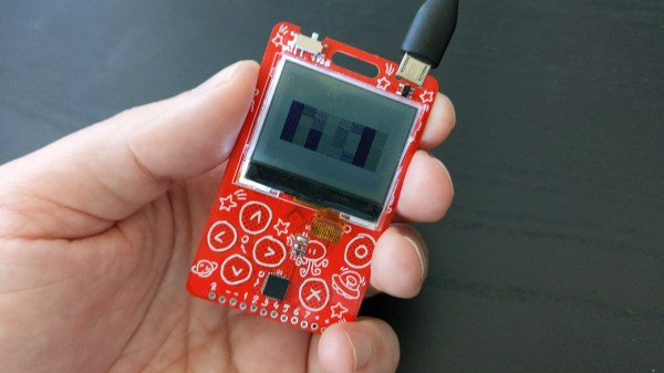

The new PewPew with an LCD showing some patterns, being held in someone's hand.

Hackaday Prize 2022: PewPew LCD Plays With Python

[deshipu] aka [Radomir Dopieralski] has been building educational handhelds for a good part of a decade now, and knows how to design hardware that makes for effective teaching. Today, we are graced with the PewPew LCD project, latest in the PewPew student-friendly handheld series, powered by CircuitPython.

The PewPew LCD from the other side, showing the simple PCB-built-in CR2032 battery holderThe goal for all of these devices has been consistent — making game programming accessible and fun. This time, as an entry in the Reuse, Recycle, Revamp round of Hackaday Prize, the new PewPew receives an upgrade – from an 8×8 LED matrix to an LCD display. This might not sound like much, but the change of display technology itself isn’t the main point. [deshipu] is working on ways to bring down the price and assembly complexity of PewPew handhelds, and he’s found there’s plenty of old stock RH-112 displays, previously used on cellphones like Nokia 1202, which these days go for as little as $1.30 a piece.

It’s exceptionally simple to get into writing games for the PewPew – one of the reasons why it’s a strong platform for workshops and individual learning. There’s already a slew of games and tutorials, and we can’t wait to see all the cool games people can build when given all the extra pixels! And, of course, we appreciate setting an example for giving new life to old displays – displays that’d otherwise inevitably end up in a trash container behind a warehouse in China.

The Reuse, Recycle, Revamp Hackaday Prize 2022 round is going on for two more weeks. If you’re making good use of something that would otherwise be discarded, please do share it with us, so that we can all learn and draw inspiration from your projects!

Resulting tweezer assembly, with a 3D printed replacement case for both of the probes

Hackaday Prize 2022: Glue-Hindered Smart Tweezer Repair Involves A Rebuild

[Dan Julio] owns a pair of Miniware multimeter tweezers, a nifty helper tool for all things SMD exploration. One day, he found them broken – unable to recognize any component between the two probes. He thought it could be a broken connection problem, and decided to take them apart. Presence of some screws on their case fooled him – in the end, it turned out that the case was glued together, and could only be opened destructively. For an entry in the “Reuse, Recycle, Revamp” round of 2022 Hackaday Prize, he tells us how he brought these tweezers back from the dead.

During the disassembly, he broke a custom flexible PCB, which wasn’t reassuring either. However, that was no reason to give up – he reverse-engineered the connections and the charging circuitry, then assembled parts of the broken tweezers together using a small generic protoboard as a base. Indeed, it was likely a broken connection between probes, because the reassembled tweezers worked!

Of course, having exposed PCBs wouldn’t do, and from the very start, assembling these tweezers back together was not an option. Instead, he developed a replacement case in OpenSCAD, bringing the tweezers back to life as his trusty tool – and still leaving repairability on the table. If you’re interested in the details, he goes more into how these tweezers are designed when it comes to charging and connectivity, and we recommend that you give his write-up a read!

We’ve been seeing smart tweezers around for over a decade now, from reviews and hacks of commercially made ones, to DIY chopstick-based and PCB-based ones. If you already own a pair of tweezers you’ve grown attached to, you can neatly retrofit them with a capacitance sensing function!

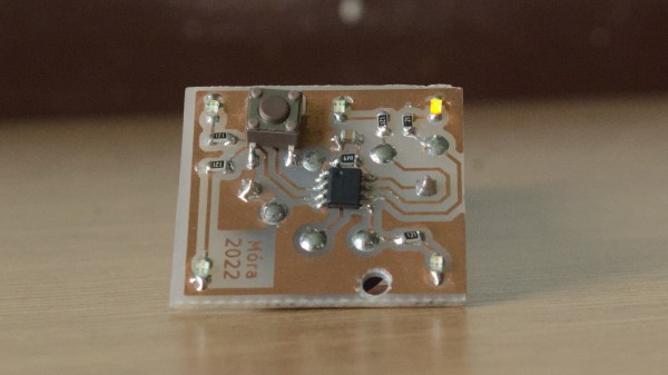
An ATTiny board that one of the students developed for this project, etched on single-sided FR4.

Electronics And C++ Education With An ATTiny13

When [Adam, HA8KDA] is not busy with his PhD studies, he mentors a group of students interested in engineering. To teach them a wide range of topics, he set out to build a small and entertaining embedded project as they watch and participate along the way. With this LED-adorned ATTiny13A project, [Adam] demonstrated schematic and PCB design, then taught C++ basics and intricacies – especially when it comes to building low-footprint software – and tied it all together into a real-world device students could take home after the project. His course went way beyond the “Hello world”s we typically expect, and some of us can only wish for a university experience like this.

He shares the PCB files and software with us, but also talks about the C++20 framework he’s developed for this ATTiny. The ATTiny13A is very cheap, and also very limited – you get 1K of ROM and 64 bytes of RAM. This framework lets you make good use of it, providing the basics like GPIO wiggling, but also things like low-power operation hooks, soft PWM with optional multi-phase operation support and EEPROM access. Students could write their own animations for this device, and he includes them in the repo, too!

In educational projects, it pays to keep code direct and clean, cruft-less and accessible to students. These are the things you can only achieve when you truly understand the tools you’re working with, which is the perfect position for teaching about them! [Adam] intends to show that C++ is more than suitable for low-resource devices, and tells us about the EEPROM class code he wrote – compiling into the same amount of instructions as an Assembly implementation and consuming the same amount of RAM, while providing compile-time checks and fail-safe syntax.

We’ve talked about using C++ on microcontrollers before, getting extra compile-time features without overhead, and this project illustrates the concept well. [Adam] asks us all, and especially our fellow C++ wizards, for our opinions on the framework he designed. Could you achieve even more with this simple hardware – make the code more robust, clean, have it do more within the limited resources?

What could you build with an ATTiny13, especially with such a framework? A flashy hairclip wearable, perhaps, or a code-learning RF-remote-controlled outlet. We’ve also seen a tiny camera trigger for endurance races,, a handheld Flappy Bird-like console, and many more!

NVIDIA Releases Drivers With Openness Flavor

This year, we’ve already seen sizeable leaks of NVIDIA source code, and a release of open-source drivers for NVIDIA Tegra. It seems NVIDIA decided to amp it up, and just released open-source GPU kernel modules for Linux. The GitHub link named open-gpu-kernel-modules has people rejoicing, and we are already testing the code out, making memes and speculating about the future. This driver is currently claimed to be experimental, only “production-ready” for datacenter cards – but you can already try it out!

The Driver’s Present State

Of course, there’s nuance. This is new code, and unrelated to the well-known proprietary driver. It will only work on cards starting from RTX 2000 and Quadro RTX series (aka Turing and onward). The good news is that performance is comparable to the closed-source driver, even at this point! A peculiarity of this project – a good portion of features that AMD and Intel drivers implement in Linux kernel are, instead, provided by a binary blob from inside the GPU. This blob runs on the GSP, which is a RISC-V core that’s only available on Turing GPUs and younger – hence the series limitation. Now, every GPU loads a piece of firmware, but this one’s hefty!

Barring that, this driver already provides more coherent integration into the Linux kernel, with massive benefits that will only increase going forward. Not everything’s open yet – NVIDIA’s userspace libraries and OpenGL, Vulkan, OpenCL and CUDA drivers remain closed, for now. Same goes for the old NVIDIA proprietary driver that, I’d guess, would be left to rot – fitting, as “leaving to rot” is what that driver has previously done to generations of old but perfectly usable cards. Continue reading “NVIDIA Releases Drivers With Openness Flavor” →

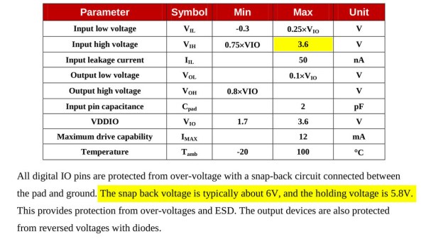
Section from the ESP8266 datasheet, showing maximum input voltage as 3.6V, but not mentioning ESD diodes to VCC and only talking about a snap-back circuit set to 6V.

Is ESP8266 5 V Tolerant? This Curve Tracer Says Yes!

Some people state that ESP8266 is tolerant of 5 V logic levels on its GPIOs, while others vehemently disagree, pointing at the datasheet-stated 3.6 V maximum. Datasheets aren’t source code for compiling the chip, however, and aren’t universally correct and complete either. [Avian] decided to dig deeper into the claims, conduct an experiment with an actual ESP8266 chip, then share the results for all of us.

For the experiment, he used a curve tracer – a device capable of producing a wide range of voltages and measuring the current being consumed, then plotting the voltage-to-current relationship. This helps characterize all sorts of variables, from diode breakdown voltages to transistor characteristics. The curve tracer he uses is a capable and professional-looking DIY build of his, and arguably, deserves a separate write-up!

The reasoning behind [Avian]’s experiment is simple – if the pin, set to an input, starts consuming a higher amount of current at a certain voltage threshold, then there’s gotta be some chip-internal structure, intended or unintended, that would be damaged at this voltage. Curve tracer in hand, he set up an ESP-01 module to set a GPIO to input, and started increasing the voltage.

A curve tracer output graph, showing that there's no noticeable increase of current consumed across the range of 0V to 6.6V - current increasing from 0.2mA to 0.4mA in that range

The tests have shown that, while there’s a reverse biased ESD diode from GPIO pins to ground, there don’t seem to be diodes from the GPIO pin to the VCC rail – and those are the primary concern for 5 V tolerance. There does seem to be something functionally akin to a 6 V Zener diode internally, which should clamp the voltage before it gets too way high for the chip to handle. None of that should be a problem for 5 V compatibility, and it seems fair to interpret this as a confirmation of 5 V tolerance until someone shows otherwise.

[Avian] didn’t want to destroy an ESP8266, so the experiment was conducted with a 1 K series resistor between the curve tracer and the input – which might have biased the results a bit. On the other hand, adding series resistors in front of your inputs is an overall underappreciated practice, 5 V or otherwise. He also points out that, while the pins don’t seem to be adversely impacted by the higher input voltage, the bootloader might set some of them to 3.3 V outputs on boot-up, shorting your 5 V source to your 3.3 V rail — worth keeping in mind!

[Avian]’s research journeys are fun to follow, and we recommend you check his blog out; last time, we covered his research of an innocent-looking 3.5 mm jack hiding a devious audio compensation circuit. Since we first covered the ESP8266 in 2014, we’ve been researching all the things it’s really capable of, and we brought up the topic of GPIO 5 V compatibility way back in 2016 – it’s reassuring to finally put this question to rest!

We thank [Adrian] for sharing this with us!

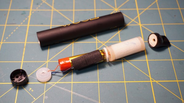
A vape pen, broken into parts, all laid out on a cutting mat

2022 Hackaday Prize: Disposable Vape Pens Turned Project Parts

Disposable vape pens, a sub-genre of electronic cigarettes, have been a fad for a few years now – they’re small self-contained devices with a rechargeable battery and some vape liquid inside. As the battery discharges and the liquid runs out, the entire vape pen is typically thrown out. [Dimitar] wants to change that, however, and teaches us how to reuse as much of the vape pen as possible — as yet another underappreciated source for parts we can use in our projects.

In an extensive worklog, he breaks down and documents a vape pen’s inner workings, coupled with a video we’ve placed below the break showing ways to disassemble them. In these, he shows how we can reuse the casing and the plastic parts, should any of us be interested in a project that happens to fit the e-cig form factor. Attention is paid to the sensor that triggers the evaporation — it may look like a microphone, but is actually a purpose-built pressure-sensor with a high-side switch! He tears into one of these in a separate video, showing how to reuse it as a capacitive touch controller. He also aiming to assemble a small database of related resources on GitHub, currently, hosting the files for the protection circuit he developed as part of his recommendations for safely reusing vape pen Li-ion batteries.

[Dimitar]’s journey is ongoing, and we can’t wait to see some fun uses for these components that he will certainly stumble upon on his way! For instance, here’s a hacker using an e-cig battery to power a pair of RGB LED-adorned sunglasses, replacing the AAAA battery they originally came with. We’ve seen hackers make guides on reusing each and every part of microwave ovens, printers and laptops, and we ourselves have talked about reusing ATX power supplies and computer mice.

Continue reading “2022 Hackaday Prize: Disposable Vape Pens Turned Project Parts” →