PicoCat, printed in yellow filament, looking at you with its ultrasonic sensor eyes

Build Your Own Cat – Some Assembly Required

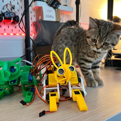
Robotic pets are sci-fi material, and [Kevin McAleer] from [Kev’s Robots] is moving us all ever so closer towards a brighter, happier, more robotic future. One of his latest robot builds, PicoCat, is a robot cat with servo-driven paws. It follows in the footsteps of the OpenCat project made by Dr. Rongzhong Li back in 2016, and we’re always happy seeing someone pick up where another hacker left off. [Kevin] took heavy inspiration from the OpenCat design – rebuilding it with hardware more friendly and accessible for makers today.

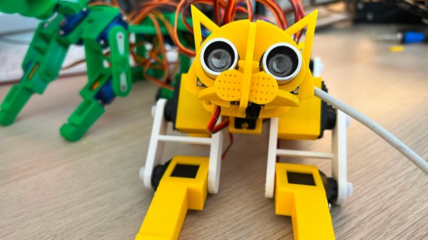
Projects like these, involving data processing and calculations to get the servos moving just right, stand to benefit from the computing power of recently released RP2040 MCU. As such, the Pimoroni Servo 2040 board is a crucial component of this build, being both the brains of the project and also a PIO-boosted driver for the eleven servos helping this robot come alive. This cat’s eyes are an ultrasonic sensor, and you can add a whole lot more sensors for any robotic intention of yours. Don’t expect this kitty to jump one meter high or scratch your favourite couch to death just yet, but there’s already a lot of potential, especially coupled with a small speaker.

A PicoCat with a non-robotic kitten in the backgroundDoes this robotic cat interest you, whether it’d be due to your sci-fi propensity or a cat hair allergy? You’re in luck, because [Kevin] is keeping things firmly in the “open-source everything” realm. MicroPython code is stored in a GitHub repo, STLs are in a .zip linked on the page, and there’s plenty of renders to never leave you confused on what goes where. With all these resources, you can source the servos and the boards, fire up your 3D printer and sit down to assemble your own PicoCat. But not just that, [Kevin] also recorded three whole streams with insights, giving us over four hours of how-it-came-to-be video material for us to learn from. First, two streams of him designing the PicoCat in Fusion360, and then, him talking about the way he creates unit tests in MicroPython to improve his robots’ reliability and significantly reduce the amount of bugs cropping up.

This is not the last we will hear from [Kevin]’s robot-filled workshop, and previously, we’ve covered his Cray-1-shaped Pi Zero cluster system and a Raspberry Pi theremin, both as open and reproducible as this kitty! As you assemble yourself a PicoCat, or perhaps a Stanford Pupper or any of the other lovely quadru-pets we’ve previously featured, you might wonder how to properly move the servos, and we’ve covered a project that teaches you specifically that.

Continue reading “Build Your Own Cat – Some Assembly Required”

A flat LiIon battery shown attached inside the gun safe, wired to the original control board

Gun Safe Made Safer With Lithium Battery Upgrade

A proper gun safe should be difficult to open, but critically, allow instant access by the authorized party.[Dr. Gerg] got a SnapSafe and discovered that, while it was quite easy to use, it would also lock the owner out easily whenever the batteries would run out. Meant to be used with four AAA batteries and no way to recharge them externally, this could leave you royally screwed in the exact kind of situation where you need the gun safe to open. This, of course, meant that the AAA batteries had to go.

Having torn a few laptop batteries apart previously, [Dr. Gerg] had a small collection of Li-ion cells on hand – cylindrical and pouch cells alike. Swapping the AAA battery holder for one of these was no problem voltage-wise, and testing showed it working without a hitch! However, replacing one non-chargeable battery with another one wasn’t a viable way forward, so he also added charging using an Adafruit LiPo charger board. One 3D printed OpenSCAD-designed bracket later, he fit the board inside the safe’s frame – and then pulled out a USB cable for charging, turning the battery into a backup option and essentially creating an UPS for this safe. Nowadays, the safe sits constantly plugged into a wall socket, and [Dr. Gerg] estimates it should last for a few weeks even in case of USB power loss.

When you read about hacking gun safes, it’s usually because of their poor security, with even biometric models occasionally falling victim to prying fingers. There’s talk about moving the locking features into the guns themselves, but we remain skeptical. “Powering an electronically locked box with internal batteries” is a fun problem, and just recently, we’ve seen it solved in a different way in this intricate voice-activated lockbox.

An unfastened piece of pipe in a drill press, rotating away

Drill Press Piece Fastening 101

What are the options you have for securing your workpiece to the drill press table? [Rex Krueger] shows us that there’s plenty, and you ought to know about them. He goes through the disadvantages of the usual C-clamps, and shows options like the regular drill press vice and a heavy-duty version that even provides a workpiece tilting mechanism, and points out small niceties like the V-grooves on the clamps helping work with round stock. For larger pieces, he recommends an underappreciated option — woodworkers’ wooden handscrew clamps, which pair surprisingly well with a drill press. Then, he talks about the hold-down drill press clamps, a favourite of his, especially when it comes to flat sheets of stock like sheet metal or plastic.

As a bonus for those of us dealing with round stock, he shows a V-block he’s made for drilling into its side, and round stock clamp, made by carefully drilling a pair of wooden hand screw clamps, for when you need to drill into a dowel from its top. The ten-minute video is a must watch for anyone not up to speed on their drill press piece fastening knowledge, and helps you improve your drilling game without having skin in it.

We’ve covered a few ingenious and unconventional drill piece fastening options before, from this wise held down by repurposed bicycle quick-release parts, to an electromagnetic wise that left our readers with mixed opinions.

Continue reading “Drill Press Piece Fastening 101”

A Pi Pico connected to a MYIR Z-turn board with a set of jumper wires

Need A JTAG Adapter? Use Your Pico!

JTAG is a powerful interface for low-level debugging and introspection of all kinds of devices — CPUs, FPGAs, MCUs and a whole lot of complex purpose-built chips like RF front-ends. JTAG adapters can be quite obscure, or cost a pretty penny, which is why we’re glad to see that [Adam Taylor] from [ADIUVO] made a tutorial on using your Pi Pico board as a JTAG adapter. This relies on a project called XVC-Pico by [Dhiru Kholia], and doesn’t require anything other than a Pi Pico board itself — the XVC-Pico provides both a RP2040 firmware implementing the XVC (Xilinx Virtual Cable) specification and a daemon that connects to the Pico board and interfaces to tools like Vivado.

First part of the write-up is dedicated to compiling the Pico firmware using a Linux VM. There’s a pre-built .uf2 binary available in the GitHub repo, however, so you don’t have to do that. Then, he compiles and runs a daemon on the PC where the Pico is connected, connects to that daemon through Vivado, and shows successful single-stepping through code on a MYIR Z-turn board with a Xilinx XC7Z020. It’s worth remembering that, if your FPGA’s (or any other target’s) JTAG logic levels are 1.8V or 2.5V-based, you will need a level shifter between it and the Pi Pico, which is a board firmly in the 3.3V realm.

You just cannot beat the $3 price and the ease of setup. Pi Pico is shaping up to be more and more of a hardware multi-tool. Just a month ago, we covered how the Pico can work as a logic analyzer. A lot of that, we have the PIO peripherals to thank for — an assembly of state machines that even let you “bitbang” high-speed interfaces like DVI. If you’re interested in how PIO functions, there are some good write-ups around here. Lacking a Pi Pico, you can use this board’s bigger sister to interface with JTAG, too.

The end result - motorized window in a silver stainless steel frame, with the linear actuators and gas struts, shown from the outside half-open.

Swing Gate Motors Come To Help For Opening A Giant Servery Window

[Martin Roberts] wrote to us, telling us about a build that his company, [Ocean View Workshop], was tasked with. Creating a four meter wide window able to open vertically is no small feat, and it had to be custom-built because the local company building such windows wasn’t comfortable working with anything other than aluminum — insufficient for the window’s scale. With massive weight of the glass alone, structural requirements for supporting it, and the mechanical loads to be applied, some careful planning was in order.

To start with, this window had to be motorized, as an average person wouldn’t be capable of pulling it upwards. Not satisfied with the linear actuator choice available, they went to a hardware store and found some swing gate actuators that, in workshop tests, proved themselves to be more than capable of handling way over the weight required. In fact, they were capable of lifting [Martin] himself off the ground without much hassle.

Continue reading “Swing Gate Motors Come To Help For Opening A Giant Servery Window”

Two pairs of boards described in the article, with toggle switches and RCA jacks, shown interconnected, LEDs on all four boards lit up.

Boards For Playful Exploration Of Digital Protocols

Teaching people efficiently isn’t limited to transmitting material from one head to another — it’s also about conveying the principles that got us there. [Mara Bos] shows us a toolkit (Twitter,
nitter link
) that you can arm your students with, creating a small playground where, given a set of constraints, they can invent and figure communication protocols out on their own.

This tool is aimed to teach digital communication protocols from a different direction. We all know that UART, I2C, SPI and such have different use cases, but why? Why are baud rates important? When are clock or chip select lines useful? What’s the deal with the start bit? We kinda sorta figure out the answers to these on our own by mental reverse-engineering, but these things can be taught better, and [Mara] shows us how.

Gently guided by your observations and insights, your students will go through defining new and old communication standards from the ground up, rediscovering concepts like acknowledge bits, bus contention, or even DDR. And, as you point out that the tricks they just discovered have real-world counterparts, you will see the light bulb go on in their head — realizing that they, too, could be part of the next generation of engineers that design the technologies of tomorrow.

Continue reading “Boards For Playful Exploration Of Digital Protocols”

The Bose headphone plug in question, with reverse-engineered schematic of the filter overlaid.

This 3.5mm Cable Distorts Signals, Hides Audio-Filtering Circuit

[Avian]’s dad got a new ham radio transceiver with a 3.5 mm jack, and his pile-of-cables got him a headphone cable from Bose headphones. He built a DB9 to 3.5 mm adapter with that one – and it failed to let data through, outputting distorted garbage of a waveform instead. With a function generator and an oscilloscope, [Avian] plotted the frequency response of the cable, which turned out to be quite far from a straight line. What was up?

Taking the connector apart was a tricky job. A combination of blunt force and a nail polish remover soak didn’t quite get them all the way, so [Avian] continued to apply blunt force and took the jack apart with minimal casualties. Turned out that there was more to the 3.5 mm plug indeed — a whole PCB with a few resistors and capacitors, reverse-engineered into the schematic seen above.

Looks like Bose decided to tweak the audio characteristics of a specific pair of headphones, and an in-plug filter was, somehow, the most efficient solution. We probably shouldn’t expect to see this often, but it bears keeping in mind: next time your repurposed 3.5 mm cable doesn’t behave as expected, it would be prudent to do a capacitance test with your trusty meter or oscilloscope.

With how small MCUs have gotten, you can easily hide more than just a few capacitors! We don’t often see circuits built into cables, but when we do, it’s for malicious purposes.