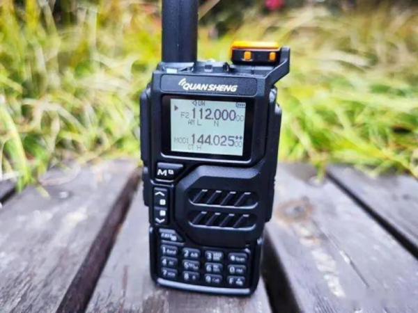
Inside A Pair Of Smart Sunglasses

If you’re willing to spend $200 USD on nothing more than 100 grams of plastic, there are a few trendy sunglasses brands that are ready to take your money before you have time to think twice. Sure, you can get a pair of sunglasses for an order of magnitude less money that do the exact same job, but the real value is in the brand stamped into the plastic and not necessarily the sunglasses themselves. Not so with this pair of Ray-Bans, though. Unlike most of their offerings, these contain a little bit more than a few bits of stylish plastic and [Becky Stern] is here to show us what’s hidden inside.

At first glance, the glasses don’t seem to be anything other than a normal pair of sunglasses, if a bit bulky But on closer inspection they hide a pair of cameras and a few other bits of electronics similar to the Google Glass, but much more subtle. The teardown demonstrates that these are not intended to be user-repairable devices, and might not be repairable at all, as even removing the hinges broke the flexible PCBs behind them. A rotary tool was needed to remove the circuit boards from the ear pieces, and a bench vice to remove the camera modules from the front frame. We can presume these glasses will not be put back together after this process.

Hidden away inside is a pair of cameras, a Snapdragon quad-core processor, capacitive touch sensors, an amplifier for a set of speakers. Mostly this is to support the recording of video and playback of audio, and not any sort of augmented reality system like Google Glass attempted to create. There are some concerning ties with Facebook associated with this product as well which will be a red flag for plenty of us around here, but besides the privacy issues, lack of repairability, and lack of features, we’d describe it as marginally less useful as an entry-level smartwatch. Of course, Google Glass had its own set of privacy-related issues too, which we saw some clever projects solve in unique ways.

Continue reading “Inside A Pair Of Smart Sunglasses”

A Dedicated GPU For Your Favorite SBC

The Raspberry Pi is famous for its low cost, versatile and open Linux environment, and plentiful I/O, making it a perfect device not only for its originally-intended educational purposes but for basically every hobbyist from gardeners to roboticists to amateur radio operators. Most builds tend to make use of the GPIO pins which allow easy connections to various peripherals and sensors, but the Pi also supports PCI devices which means that, in theory, it could use a GPU in much the same way that a modern computer would. After plenty of testing and development, [Jeff Geerling] brings us this custom graphics card interface for the Raspberry Pi.

The testing for all of these graphics cards has been done with a Pi Compute Module 4 and the end result is an interface device which looks much like a graphics card itself. It splits the PCI bus out onto a more familiar x16 slot connector and adds physical connections for power, USB, and Ethernet. When plugged into the carrier board, the Compute Module can be attached to any of a number of graphics cards, including the latest and highest-end of Nvidia and AMD offerings.

Perhaps unsurprisingly, though, the 4090 and 7900 cards don’t work with the Raspberry Pi. This is partially due to the 32-bit limitations of the Pi and other memory mapping issues, but even after attempting some workarounds Nvidia’s cards aren’t open-source enough to test properly (although the card is recognized by the Pi) and AMD’s drivers crash the system even after compiling a custom kernel. [Jeff] did find an Nvidia card that worked, although it requires using the USB interface and second-hand cards are selling for around $3000 USD. For a more economical choice there are some other graphics cards that he was eventually able to get working, albeit not with perfect performance, including some of the ones we’ve seen him test already.

Continue reading “A Dedicated GPU For Your Favorite SBC”

Holograms Display Time With ESP32

Holograms and holographic imagery are typically viewed within the frame of science fiction, with perhaps the most iconic examples being Princess Leia’s message to Obi-Wan in Star Wars, or the holodecks from Star Trek. In reality, holograms have been around for a surprising amount of time, with early holographic images being produced in the late 1940s. There are plenty of uses outside of imagery for modern holographic systems as well, and it’s a common enough technology that it’s possible to construct one using an ESP32 as well.

In this build, [Fiberpunk] demonstrates the construction and operation of a holographic clock. The image is three-dimensional and somewhat transparent and is driven by an ESP32 microcontroller. The display is based around a beamsplitter prism which, when viewed from the front, is almost completely invisible to the viewer. The ESP32 is housed in a casing beneath this prism, and [Fiberpunk] has two firmware versions available for the device. The first is the clock which displays an image as well as the time, and the second is more of a demonstration which can show more in-depth 3D videos using gcode models and also has motion sensing controls.

For anyone interested in holography, a platform like this is might make an excellent entry point to explore, and with the source for this build available becomes even easier. It’s almost certainly less expensive than these 3D printers that can turn out custom holographic images, and has the added benefit of being customizable and programmable as well.

Continue reading “Holograms Display Time With ESP32”

LoRa Goes To The Moon

LoRa is a communications method that allows for long range radio contacts to be made using typically low-powered devices. This shouldn’t be surprising given that LoRa is short for “long range” which typically involves distances on the order of a few kilometers. However, a group of students are taking the “long range” moniker to the extreme by attempting to send and receive a signal with a total path of around 768,000 kilometers by using some specialized equipment to bounce a LoRa signal off of the moon and receive it back on Earth.

Earth-Moon-Earth (EME) communications are typically done by amateur radio operators as a hobby, since the development of communications satellites largely rendered other uses of this communication pathway obsolete. A directional antenna and a signal typically on the order of 1 kW are often used to compensate for the extremely high path losses. Using LoRa, which makes use of chirp spread spectrum modulation, they hope to reduce this power requirement significantly. The signals are being generated and received on a set of HackRF One devices fed into a series of amplifiers, and the team is also employing a set of large dish antennas, one in New Jersey and another in Alaska, to send and receive the messages.

The software used is the open-source SDRAngel which is useful for controlling the HackRF and moving the LoRa signal up to 1296 MHz. Normally LoRa is operated on an unlicensed band, but this method allows for finer control of not only frequency but also bandwidth, which helps reduce the impacts of path loss. Right now they have not yet completed their contacts with the Alaska station (partially due to that antenna being covered in snow) but we hope to hear more news in the future. In the meantime, take a look at some more traditional long-range communications using this protocol with more manageable-sized antennas.

Image courtesy of NASA, Public domain, via Wikimedia Commons

New Drivers For Ancient Webcam

For those of us who are a little older, the 90s seem like they were just a few years ago. The younger folks might think that the 90s were ancient history though, and they might be right as we’ve been hearing more bands like Pearl Jam and The Offspring playing on the classic rock stations lately. Another example of how long ago the 90s were is taking a look at the technological progress that has happened since then through the lens of things like this webcam from 1999, presuming you load up this custom user space driver from [benjojo].

Thankfully the driver for this infamous webcam didn’t need to be built completely from scratch. There’s a legacy driver available for Windows XP which showed that the camera still physically worked, and there’s also a driver for Linux which was used as a foundation to start working from. From there a USB interface was set up which allowed communication to the device. Not a simple task, but apparently much easier than the next steps which involve actually interpreting the information coming from the webcam. This is where a background in digital signal processing is handy to have. First, the resolution and packet size were sorted out which led to a somewhat recognizable image. From there a single monochrome image was pieced together, and then after deconstructing a Bayer filter and adding color, the webcam is back to its former 90s glory.

[benjojo] has hosted all of the code for this project on a GitHub page for anyone who still has one of these webcams sitting around in the junk drawer. The resolution and color fidelity are about what we’d expect for a 25-year-old device that predates Skype, Facebook, Wikipedia, and Firefox. And, while there are still some things that need to be tweaked such as the colors, white balance, and exposure, once that is sorted out the 90s and early 00s nostalgia is free to flood in.

Hinges Live Inside 3D Prints

Since desktop 3D printers have become more common, we’ve seen dramatic shifts in all kinds of areas such as rapid prototyping, antique restoration, mass production of consumer goods, or even household repairs that might not have been possible otherwise. There are a lot of unique manufacturing methods that can be explored in depth with a 3D printer as well, and [Slant 3D] demonstrates how one such method known as the living hinge can be created with this revolutionary new tool.

Living hinges, unlike a metal hinge you might pick up at a hardware store, are integrated into the design of the part and made of the same material. Typically found in plastic containers, they allow for flexibility while keeping parts count and cost low. The major downside is that they create stresses in the materials when used, so their lifespan is finite. But there are a number of ways to extend their life, albeit with a few trade-offs.

The first note is to make sure that you’re using the right kind of plastic, but after that’s taken care of [Slant 3D] builds a few flexible parts starting with longer circular-shaped living hinge which allows greater range of motion and distributes the forces across a wider area, at a cost of greater used space and increased complexity. A few other types of living hinges are shown to use less space in some areas, but make the hinges only suitable for use in other narrower applications.

One of the more interesting living hinges he demonstrates is one that’s more commonly seen in woodworking, known there as a kerf bend. By removing strips of material from a sheet, the entire sheet can be rotated around the cuts. In woodworking this is often done by subtracting material with a CNC machine or a laser cutter, but in 3D printing the voids can simply be designed into the part.

Continue reading “Hinges Live Inside 3D Prints”

High Voltage Power Supply From USB

Those who work in different spaces may have different definitions of the term “high voltage”. For someone working on the GPIO pins of a Raspberry Pi it might be as little as 5 volts, someone working on a Tesla coil might consider that to be around 20 kV, and an electrical line worker might not reference something as HV until 115 kV. What we could perhaps all agree on, though, is that getting 300 volts out of a USB power supply is certainly a “high voltage” we wouldn’t normally expect to see in that kind of context, but [Aylo6061] needed just such a power supply and was eventually able to create one.

In this case, the high voltages will eventually be used for electrophoresis or electrowetting. But before getting there, [Aylo6061] has built one of the safest looking circuits we’ve seen in recent memory. Every high voltage part is hidden behind double insulation, and there is complete isolation between the high and low voltage sides thanks to a flyback converter. This has the benefit of a floating ground which reduces the risk of accidental shock. This does cause some challenges though, as voltage sensing on the high side is difficult while maintaining isolation, so some clever tricks were implemented to maintain the correct target output voltage.

The control circuitry is based around an RP2040 chip and is impressive in its own right, with USB isolation for the data lines as well. Additionally the project code can be found at its GitHub page. Thanks to a part shortage, [Aylo6061] dedicated an entire core of the microprocessor to decoding digital data from the high voltage sensor circuitry. For something with a little less refinement, less safety, and a much higher voltage output, though, take a look at this power supply which tops its output voltage around 30 kV.