Adding a resin printer to one’s workbench has never looked so attractive, nor been so affordable. Complex shapes with effortlessly great detail and surface finish? Yes, please! Well, photos make the results look effortless, anyway. Since filament-based printers using fused deposition modeling (FDM) get solid “could be better” ratings when it comes to surface finish and small detail resolution, will a trusty FDM printer end up retired if one buys a resin printer?
The short answer is this: for users who already use FDM, a resin-based stereolithography (SLA) printer is not likely to take over. What is more likely to happen is that the filament printer continues to do the same jobs it is good at, while the resin printer opens some wonderful new doors. This is partly because those great SLA prints will come at a cost that may not always justify the extra work.
Let’s go through what makes SLA good, what it needs in return, and how it does and doesn’t fit in with FDM.
[Flameeyes] has heard complaints (and at times, he admits, has complained himself) about big companies not contributing improvements to projects they seem to find useful, or rolling their own implementation rather than use and contribute to an existing code base. Having recently left Google after seven years, he has some insights into some of the reasons big corporations (at least Google, anyway) may sometimes seem to eschew making code contributions, and some of the reasons might come as a surprise.
The biggest issue is the software license. Without one, there is no legal structure to use, distribute, or contribute to the code, and no corporate entity will want to touch it. Google specifically forbids creating patches for projects with either no license, or incompatible licenses. An example of an incompatible license is one that forbids commercial use, because everything a corporation like Google does — even research –is considered a commercial endeavor. In addition, on the corporate side making contributions might trigger a code review process of some kind for some licenses, but not for others. [Flameeyes] suggests the MIT license as one that is acceptable to pretty much everyone with a minimum of fuss. Another caution: if a project’s code resides in an online repository, make sure the repository is licensed as well.
A few other small suggestions (such as maintaining an AUTHORS file to track contributors in a tidy way) rounds out the advice. It sounds simple, but software licensing is so critical to the whole affair that it’s important to get it right — he suggests the REUSE tool for anyone wanting to make sure a project’s licensing is tidy.
[Flameeyes] makes a point that none of this guidance is based on secret or institutional knowledge. Google has a public document detailing exactly how they use and deal with open source, and it’s a solid guide for how to make your project more accepting of contributions from a corporate entity like Google. (Or, if you prefer, a guide on how to set up as many barriers as possible for your project.)
In case you missed it, we just want to remind you that our favorite recent open source project from Google is definitely Pigweed.
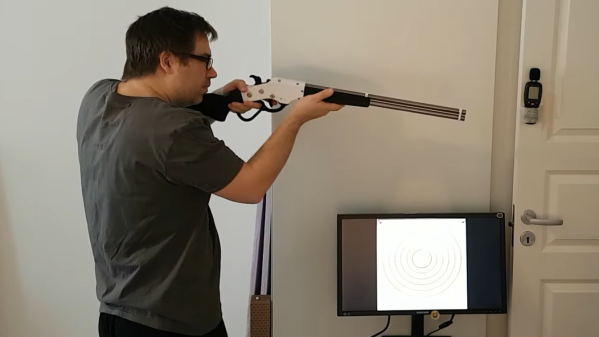
[Dirk] shared a fascinating project of his that consists of several different parts coming together in a satisfying whole. It’s all about wanting to do target practice, indoors, using a simple red laser dot instead of any sort of projectile. While it’s possible to practice by flashing a red laser pointer and watching where it lands on a paper target, it’s much more rewarding (and objective) to record the hits in some way. This is what led [Dirk] to create human-powered, battery-free laser guns with software to track and display hits. In the image above, red laser hits on the target are detected and displayed on the screen by the shooter.
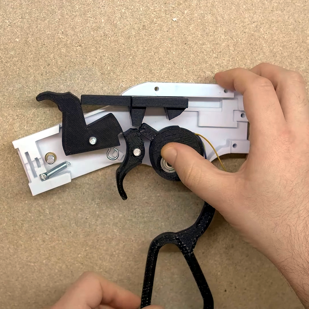
Right under the thumb is the pivot point for the lever, and that’s also where a geared stepper motor (used as a generator) is housed. Operating the action cranks the motor.
There are several parts to this project and, sadly, the details are a bit incomplete and somewhat scattered around, so we’ll go through the elements one at a time. The first is the guns themselves, and the star of the show is his 3D printed cowboy rifle design. The rifle paints the target with a momentary red laser dot when the trigger is pressed, but that’s not all. [Dirk] appears to have embedded a stepper motor into the lever action, so that working the lever cranks the motor as a generator and stores the small amount of power in a capacitor. Upon pulling the trigger, the capacitor is dumped into the laser (and into a piezo buzzer for a bit of an audio cue, apparently) with just enough juice to create a momentary flash. We wish [Dirk] had provided more details about this part of his build. There are a few more images here, but if you’d like to replicate [Dirk]’s work it looks like you’ll be on your own to some extent.
As for the target end of things, blipping a red dot onto a paper target and using one’s own eyeballs can do the job in a bare minimum sort of way, but [Dirk] went one further. He used Python and OpenCV with a camera to watch for the red dot, capture it, then push an image of the target (with a mark where the impact was detected) to a Chromecast-enabled screen near the shooter. This offers much better feedback and allows for easier scoring. The GitHub repository for the shot detector and target caster is here, and while it could be used on its own to detect any old laser pointer, it really sings when combined with the 3D printed cowboy rifle that doesn’t need batteries.
Not using projectiles in target practice does have some benefits: it’s silent, it’s easy to do safely, there is no need for a backstop, there are no consumables or cleaning, and there is no need to change or patch targets once they get too many holes. Watch it all in action in the video embedded below.
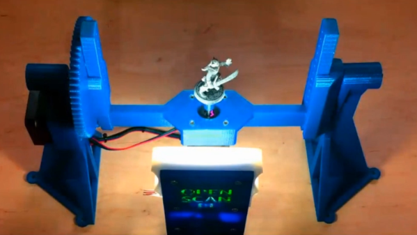
The OpenScan project has been updated quite a bit since its inception. OpenScan is an open source, Arduino or Raspberry Pi-based 3D scanner for small objects that uses 3D printed hardware and some common electronic components to create 3D scans using photogrammetry; a process by which a series of still images from different angles are used to create a 3D point cloud of an object, which can then be used to generate a 3D model.
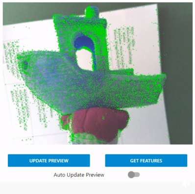
Feature visualization overlays detected features onto the camera preview to help judge quality. Broadly speaking, green is good.
Photogrammetry is a somewhat involved process that relies on consistent conditions, so going through the whole process only to find out the results aren’t up to snuff can be tiresome. Happily, OpenScan offers some interesting new functions such as feature visualization via the web interface, which helps a user judge scan quality and make changes to optimize results without having to blindly cross their fingers quite so much. OpenScan remains a one-person project by [Thomas], who is clearly motivated to improve his design and we’re delighted to see it getting updates.
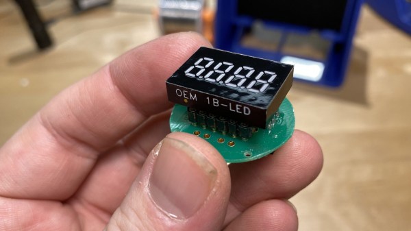
[JGlass] deals with public-facing technology, which he says includes things like theatre equipment, retail displays, and museum displays. Many of these pieces of technology are literally one-of-a-kind devices, even if they were constructed from what was once off-the-shelf, commercially available parts. When these machines need servicing, replacement parts aren’t always available, and reverse engineering comes in handy. He recently began documenting exactly how to approach this process by using the identification and replacement of an obsolete 7-segment industrial display as an example.
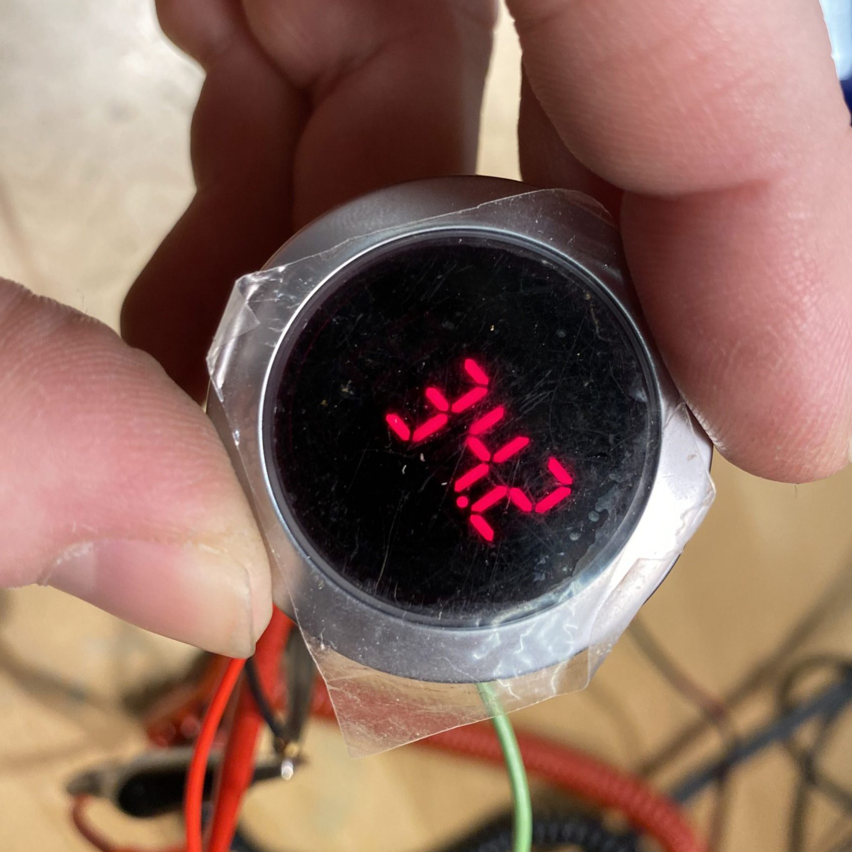
The particular part shown is the Lascar EM32-4-LED, which up and died in a unique piece of equipment. The trouble is that the EM32-4-LED is out of production and unobtainable, and the Programmable Logic Controller (PLC) that drives the whole thing is a black box that cannot be modified. It’s very good news that a datasheet exists, but that’s often just a starting point. To create a one-off, drop-in solution requires a combination of research, troubleshooting, and design work.
To do this, [JGlass] starts off by walking through datasheet elements and explains that it’s important to build a high level understanding of function first, then drill down into details, and always be ready to verify, challenge, or throw out one’s assumptions. After establishing a high level understanding comes matching physical evidence to things like block and functional diagrams, then cracking open the faulty component to see if anything else can be learned. Only then are multimeters and probes taken out for more active research. All of this sleuthing must always be done with the end goal firmly in mind: creating a new device that acts like the one being replaced. Without focus, one can easily get lost in details and unknowns.
Reverse Engineering is a process, and the more tools, the better. If you missed our earlier post about a hacker’s guide to JTAG, here’s your chance to check it out and be all the more prepared for the next time you need to do some electron detective work of your own.
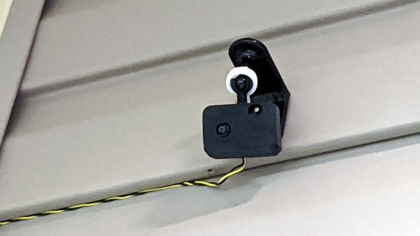
There are several different paths to a smart home, and [Marcus] eventually settled on using ESPHome and ESP8266/ESP32 based devices to create a complete DIY smart home solution which covers his garage door, sprinklers, LED strips, light bulbs, and outlets. There’s even an experimental (and very economical) ESP32-CAM based camera, shown here.
In fact, [Marcus]’s write-up could double as a sort of reference design. If you’re curious about ESPHome, be sure to read what he has to say because he explains exactly how he configured each device and any challenges he encountered in the process.
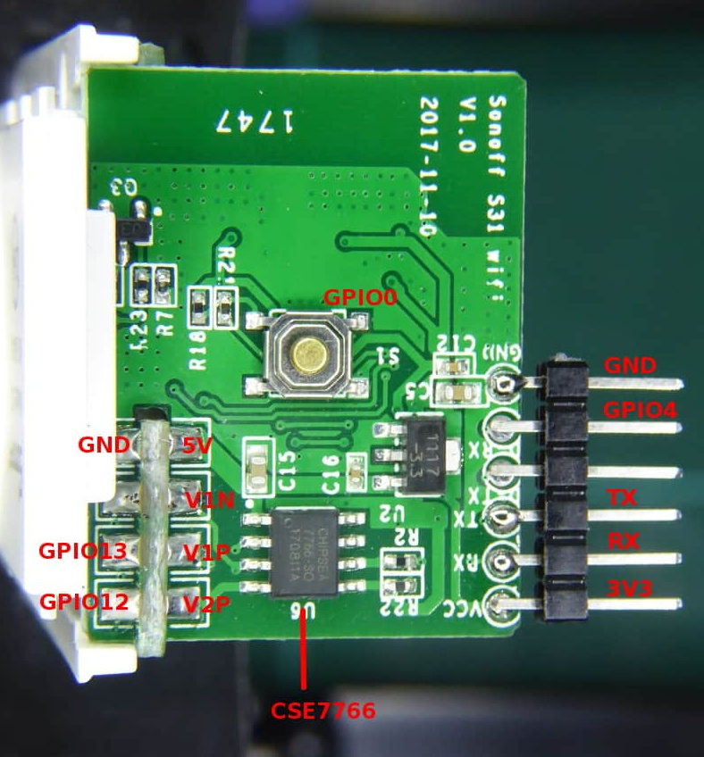
Beyond the software guidance, the post is also a great resource on how to flash a new firmware onto several different smart devices. [Marcus] provides nicely labeled images of the boards that show where you need to connect your programmer, which just might save you some trouble down the line. Though he did manage to set fire to one of the bulbs, so keep an eye out for that.
When it comes to manufacturing, sheet metal and injection molding make the world go ’round. As a manufacturing method, injection molding has its own range of unique design issues and gotchas that are better to be aware of than not. To help with this awareness, [studiored] has a series of blog posts describing injection molding design issues, presented from the perspective of how to avoid and address them.
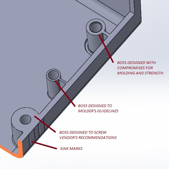
Design of screw bosses demonstrating conflict between molder’s guidelines and vendor’s recommendations. Compromising between both is a science and an art.
Because injection molding involves heat, warp is one issue to be aware of and its principles will probably be familiar to anyone with nitty-gritty experience in 3D printing. Sink marks are also an issue that comes down to differential cooling causing problems, and can ruin a smooth and glossy finish. Both of these play a role in how best to design bosses.
Minimizing and simplifying undercuts (similar to overhangs in 3D printer parlance) is a bit more in-depth, because even a single undercut means much more complex tooling for the mold. Finally, because injection molding depends on reliably molding, cooling, and ejecting parts, designing parts with draft (a slight angle to aid part removal) can be a fact of life.
[studiored] seems to have been working overtime on sharing tips for product design and manufacture on their blog, so it’s worth keeping an eye on it for more additions. We mentioned earlier that much of the manufacturing world revolves around injection molding and sheet metal, so to round out your knowledge we published a primer on everything you need to know about the art and science of bending sheet metal. With a working knowledge of the kinds of design issues that affect these two common manufacturing methods, you’ll have a solid foundation for any forays into either world.