
Smartphone Case Doubles As Chording Keyboard, With Gesture Inputs

Smartphones and other modern computing devices are wonderful things, but for those with disabilities interacting with them isn’t always easy. In trying to improve accessibility, [Dougie Mann] created TypeCase, a combination gestural input device and chording keyboard that exists in a kind of symbiotic relationship with a user’s smartphone.

With TypeCase, a user can control a computer (or the smartphone itself) with gestures, emulate a mouse, or use the device as a one-handed chording keyboard for text input. The latter provides an alternative to voice input, which can be awkward in public areas.

The buttons and motion sensors allow for one-handed button and gestural input while holding the phone, and the Bluetooth connectivity means that the device acts and works just like a wireless mouse or keyboard. The electronics consist mainly of an Adafruit Feather 32u4 Bluefruit LE, and [Dougie] used 3D Hub’s on-demand printing service to create the enclosures once the design work was complete. Since TypeCase doubles as a protective smartphone case, users have no need to carry or manage a separate device.

TypeCase’s use cases are probably best expressed by [Dougie]’s demo video, embedded below. Chording keyboards have a higher learning curve, but they can be very compact. One-handed text input does remind us somewhat of a very different approach that had the user make gestures in patterns reminiscent of Palm’s old Graffiti system; perhaps easier to learn but not nearly as discreet.

Continue reading “Smartphone Case Doubles As Chording Keyboard, With Gesture Inputs”

Watch Legged Robot Run Circles Around Its Bigger Brethren

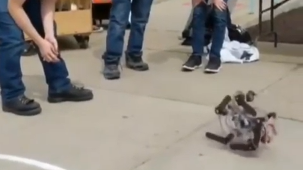
[Ben Katz] posted about bringing the Mini Cheetah (center, above) robot to the 2019 International Conference on Robotics and Automation (ICRA) held in Montréal, where it shared the floor with others for a workshop focusing on real-world deployment of legged robots. Those of you who haven’t been keeping up with legged robots may find yourselves delightfully surprised at the agility and fluid movements of this robot. Mini Cheetah may lack the effectors or sensors of the bigger units, but its nimbleness is undeniable.

[Ben] shared some footage of the robots together, and at about 7:22 in this video Mini Cheetah can be seen showing off a bit of flexing, followed by running around a larger unit. Another, shorter video is embedded below where you can see all the attendees moving about in a rare opportunity see them all together. You can even see the tiny one-legged hopping robot Salto if you watch closely!

Continue reading “Watch Legged Robot Run Circles Around Its Bigger Brethren”

Basic Acrylic Bending, No Special Tools Needed

Acrylic sheets are relatively inexpensive, pretty, and can be heat-shaped very effectively. There are blades and tools made specifically for cutting, heating, and bending acrylic but [Marija] shows that even without them acrylic can be cut and bent with a bit of care and patience.

Acrylic sheets are brittle and crack easily, but a hacksaw is a good way to cut it by hand. After cutting, [Marija] uses a small portable gas stove at its lowest setting to provide gentle heat until the acrylic becomes soft, then it can be formed into different shapes using common shop and household items. It’s a process that requires patience and practice, so she shares some useful tips:

  • Remove the protective film after cutting, but before heat forming. Otherwise the film will be much harder to remove.
  • Heating too aggressively will result in bubbles that ruin the acrylic.
  • Uneven heating will result in a bad bend, or “hot spots” which can result in bubbles as mentioned above.
  • This heating method naturally softens a wide area, but it’s still possible to get straight and flat bends by using wood forms and letting the acrylic cool before moving it.

[Marija] used this method of heating and bending acrylic to complete an earlier lamp project of hers that we featured in the past. Acrylic might laser-cut beautifully, and there may be inexpensive tools for heating and bending it, but it’s always nice to have some tried and true techniques that don’t require anything special.

Continue reading “Basic Acrylic Bending, No Special Tools Needed”

These Tips Make Assembling A Few Hundred PCBs Easier

There are a few common lessons that get repeated by anyone who takes on the task of assembling a few hundred PCBs, but there are also unique insights to be had. [DominoTree] shared his takeaways after making a couple hundred electronic badges for DEFCON 26 (that’s the one before the one that just wrapped up, if anyone’s keeping track.) [DominoTree] assembled over 200 Telephreak badges and by the end of it he had quite a list of improvements he wished he had made during the design phase.

Some tips are clearly sensible, such as adding proper debug and programming interfaces, or baking an efficient test cycle into the firmware. Others are not quite so obvious, for example “add a few holes to your board.” Holes can be useful in unexpected ways and cost essentially zero. Even if the board isn’t going to be mounted to anything, a few holes can provide a way to attach jigs or other hardware like test fixtures.

[DominoTree] ended up having to attach multiple jumper wires to reprogram boards after assembly, and assures us that “doing this a bunch of times really sucked.”
Other advice is more generic but no less important, as with “eliminate as many steps as possible.” Almost anything adds up to a significant chunk of time when repeated hundreds of times. To the basement hacker, something such as pre-cut and pre-tinned wires might seem like a shameful indulgence. But cutting, stripping, tinning, then hand-soldering a wire adds up to significant time and effort by iteration number four hundred (that’s two power wires per badge) even if one isn’t staring down a looming deadline.

[DominoTree] also followed up with additional advice on making assembly easier. Our own [Brian Benchoff] has also shared his observations on the experience of developing and assembling a large number of Hackaday Superconference badges, including what it took to keep things moving along when inevitable problems surfaced.

You don’t need to be making batches of hundreds for these lessons to pay off, so keep them in mind and practice them on your next project.

DIY Watertight Junction Box For Serious Outdoor Sealing

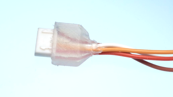
Thingiverse user [The-Mechanic] shared a design for 3D printed enclosures that are made to house wire and cable junctions, which can then be rendered weatherproof by injecting them with a suitable caulking compound and allowing it to cure. It’s a cross between an enclosure and potted electronics. It’s also a one-way trip, because the result is sealed up like a pharaoh’s tomb. On the upside, it’s cheap, accessible, and easily customized.

The way it works is this: wires go through end caps which snap onto the main body, holding the junction inside. Sealant is then pumped in via the hole on the side, then the hole is plugged. Afterwards, all there is to do is wait until the sealant cures. [The-Mechanic] has a couple of companion designs, as well. For tubes of sealant that have threaded tops, one can more effectively save the contents of the tube for later with this design for screw-on caps. There are also 3D printed nozzles in a variety of designs.

One thing to keep in mind about silicone-based sealants is that thick gobs of it can take a really, really long time to cure fully. A thick gob of the stuff will tend to firm up on the outside but leave the inside gooey. If that will be a problem, maybe take a cue from Oogoo and mix in a bit of corn starch with the silicone sealant. The resulting mixture will be thicker, but it’ll cure throughout with no problems.

One-Motor Domino Laying Machine Works For Tips

[Gzumwalt] did things a little differently with his Pink and Green Domino Machine II, a 3D printed device that drops dominoes in a neat row ready for toppling over. Unlike his earlier version, this one holds dominoes laying flat in a hopper that’s accessible from the top for easy loading. The previous unit had an elegance to it, but it was more limited with respect to how many dominoes it could hold at a time. This new version solves that problem while also showing off a slick mechanism that gracefully slides a domino from the bottom of the hopper, then gently positions it standing on end before opening a rear door to let it out as it moves to the next position. One of the interesting things [gzumwalt] discovered when designing this device was that there isn’t really a “standard” size of domino. That’s one of the reasons the demo uses 3D printed blocks.

Pulling this off with a single small DC motor is a remarkable achievement; the mechanism even stably ejects a positioned domino from the rear without halting its forward motion in the process. An animation of how the mechanism works is embedded below, be sure to check it out!

Continue reading “One-Motor Domino Laying Machine Works For Tips”

(Mis)use This Part To Attach 3D Printed Stuff To A Shaft

Interfacing a shaft to a 3D printed gear doesn’t have to be tricky. [Tlalexander] demonstrated a solution that uses one half of a spider coupling (or jaw coupling) to create an effective modular attachment. The picture above (and this older link) shows everything you need to know: the bottom of the coupling is mounted to the shaft, and a corresponding opening is modeled into the the 3D printed part. Slide the two together, and the result is a far sturdier solution than trying to mate a 3D printed gear directly to a motor shaft with a friction fit or a screw. This solution isn’t necessarily limited to attaching gears either, any suitable 3D printed part could be interfaced to a shaft in this way.

These couplings are readily available, and fortunately for hobbyists, come in sizes specifically designed for common stepper motors like NEMA 17 and NEMA 23. Ironically, these couplings are often used when building custom 3D printers for those same reasons. With this method interfacing anything at all to a motor shaft becomes mostly a matter of modeling a matching hole out of the part to be 3D printed. One coupling even provides two such attachments, since only one of the two sides is used.

The image up top is from [Tlalexander]’s Rover image gallery, which contains a ton of fantastic pictures of the work that went into the gearboxes, a major part of the Rover’s design that we’ve seen in the past.