3D Print Springs With Hacked GCode

If you’ve used a desktop 3D printer in the past, you’re almost certainly done battle with “strings”. These are the wispy bits of filament that harden in the air, usually as the printer’s nozzle moves quickly between points in open air. Depending on the severity and the material you’re printing with, these stringy interlopers can range from being an unsightly annoyance to triggering a heartbreaking failed print. But where most see an annoying reality of pushing melted plastic around, [Adam Kumpf] of Makefast Workshop sees inspiration.
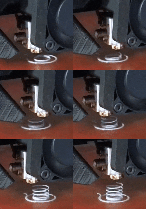
Noticing that the nozzle of their printer left strings behind, [Adam] wondered if it would be possible to induce these mid-air printing artifacts on demand. Even better, would it be possible to tame them into producing a useful object? As it turns out it is, and now we’ve got the web-based tool to prove it.

As [Adam] explains, you can’t just load up a 3D model of a spring in your normal slicer and expect your printer to churn out a useful object. The software will, as it’s designed to do, recognize the object can’t be printed without extensive support material. Now you could in theory go ahead and print such a spring, but good luck getting the support material out.

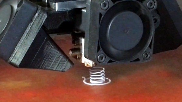
The trick is to throw away the traditional slicer entirely, as the layer-by-layer approach simply won’t work here. By manually creating GCode using carefully tuned parameters, [Adam] found it was possible to get the printer to extrude plastic at the precise rate at which the part cooling fan would instantly solidify it. Then it was just a matter of taking that concept and applying it to a slow spiral motion. The end result are functional, albeit not very strong, helical compression springs.

But you don’t have to take their word for it. This research has lead to the creation of an online tool that allows you to plug in the variables for your desired spring (pitch, radius, revolutions, etc), as well as details about your printer such as nozzle diameter and temperature. The result is a custom GCode that (hopefully) will produce the desired spring when loaded up on your printer. We’d love to hear if any readers manage to replicate the effect on their own printers, but we should mention fiddling with your printer’s GCode directly isn’t without its risks: from skipping steps to stripped filament to head crashes.

The results remind us somewhat of the 3D lattice printer we featured a couple of years back, but even that machine didn’t use standard FDM technology. It will be interesting to see what other applications could be found for this particular technique.
Continue reading “3D Print Springs With Hacked GCode”

Mastering OpenSCAD Workflow

As you may have noticed in our coverage, we’re big fans of OpenSCAD around these parts. The fact that several of the Hackaday writers organically found and started using the parametric CAD package on their own is not only a testament to our carefully cultivated hive mind but also to the type of people it appeals to. Hackers love it because it allows you to model physical objects as if you were writing software: models are expressed in code, and its plain text source files can be managed with tools like git and make. If you’re a real Pinball Wizard you could design objects and export them to STL without ever using a graphical interface.

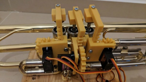
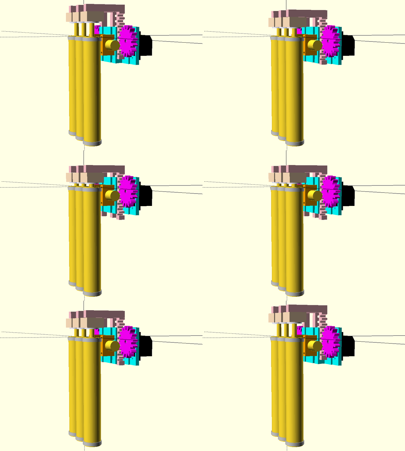
But as you might expect, with such power comes a considerable learning curve. OpenSCAD devotee [Uri Shaked] recently wrote in to share with us his workflow for designing complex interacting mechanisms, which serves as an excellent primer to the world of parametric design. From animating your models to recreating the “vitamins” of your build, his post contains plenty of tips that can help both new and veteran OpenSCAD users alike.

Perhaps the biggest takeaway from his post is that you should be thinking of your projects as a whole, rather than as individual models. [Uri] recalls his early attempts at designing mechanisms: designing each component individually, printing it out, and only then finding out if it fits together with the other pieces. This method of trial and error is probably familiar to anyone who’s designed their own 3D printed parts — but it’s slow and wastes materials. The alternative, as he explains it, is to design all of the pieces at the same time and “assemble” them virtually. This will allow you to check clearances and fitment without dedicating the time and materials to test it in the real world.

In fact, as [Uri] explains, you’re better off spending your time bringing real-world parts into OpenSCAD. By carefully measuring the hardware components you want to interact with (servos, gears, switches, etc), you can create facsimiles of them to use as a reference in your OpenSCAD project. As time goes on, you can build up your own library of drop-in reference models which will accelerate future designs.

He also spends a little time talking about something that doesn’t seem to be terribly well known even among the OpenSCAD converts: you don’t have to use the built-in editor if you don’t want to. Since OpenSCAD source code files are plain text, you can write them in whatever editor you like. The OpenSCAD model viewer even has an option specifically for this scenario, which will cause it to update the rendered preview as soon as it detects the source has been updated. For [Uri] this means he can create his designs in Visual Studio Code with a constantly updating preview in another window.

If you’re looking for examples of what the parametric capabilities of OpenSCAD can do for you, we’ve got no shortage of excellent examples. From creating customized computer cases to saving time by using mathematically derived components. Our very own [Elliot Williams] even has a write up about that most glorious of OpenSCAD commands: hull().

ESP8266 Wi-Fi Instant Camera Is A Simple Shooter

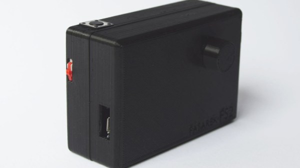
If a camera that combines the immediate gratification of a Polaroid with cloud hosting sounds like something that tickles your fancy, look no farther than this ESP-powered point and shoot camera created by [Martin Fasani]. There’s no screen or complicated configuration on this camera; just press the button and the raw picture pops up on the online gallery. Somehow it’s simultaneously one of the most simplistic and complex implementations of the classic “instant camera” concept, and we love it.

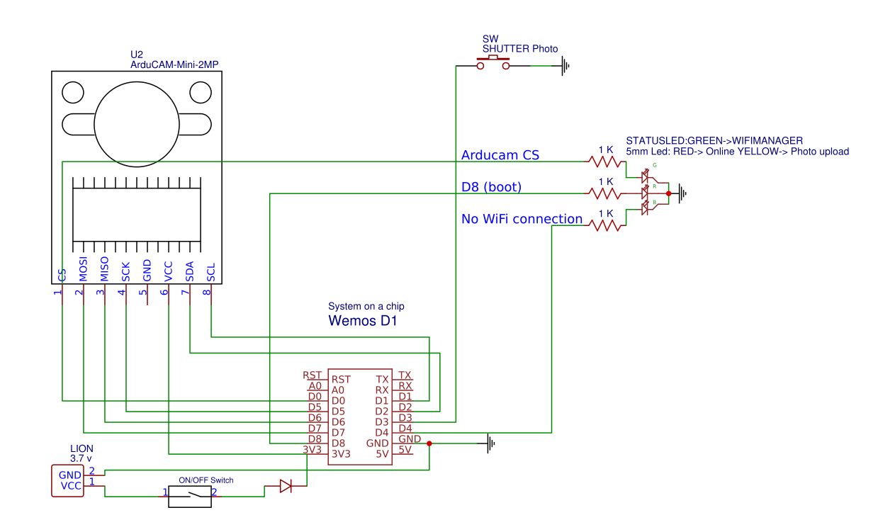
The electronics in the camera itself, which [Martin] calls the FS2, is quite simple. At the core, it’s nothing more than the ESP board, an ArduCAM camera module, and a momentary button for the shutter. To make it portable he added a 2000 mAh Li-ion battery and an Adafruit Micro Micro USB charger. [Martin] added support for an optional 128×64 OLED display for user feedback. Everything is housed in a relatively spacious 3D printed enclosure, leaving some room for possible future hardware.

There are firmware versions for both the ESP8266 and ESP32, so fans of either generation of the popular microcontroller are invited to the party. Processing images is obviously a bit faster if you go with the more powerful 32-bit chip, but on the flip side the ESP8266 uses 3MB of SPI flash as a local buffer for the images during upload, which helps prevent lost images if there’s a problem pushing them to the cloud. The camera is intended to be as simple as possible so right now the only option other than taking still images is a time-lapse mode. [Martin] hopes to implement some additional filters and effects in the future. He’s also hoping others might lend a hand with his firmware. He’s specifically looking for assistance getting autofocus working and implementing more robust error correction for image uploads.

We’ve seen some impressive DIY camera builds using everything from a salvaged thermal sensor to film and molten aluminum. But the quaint simplicity of what [Martin] has put together here really puts his project in a whole new category.

Continue reading “ESP8266 Wi-Fi Instant Camera Is A Simple Shooter”

The How And Why Of Laser Cutter Aiming

Laser aficionado [Martin Raynsford] has built up experience with various laser cutters over the years and felt he should write up a blog post detailing his first-hand findings with an often overlooked aspect of the machines: aiming them. Cheap diode laser cutters and engravers operate in the visible part of the spectrum, but when you get into more powerful carbon dioxide lasers such as the one used in the popular K40 machines, the infrared beam is invisible to the naked eye. A secondary low-power laser helps to visualize the main laser’s alignment without actually cutting the target. There are a couple of ways to install an aiming system like this, but which way works better?

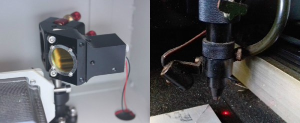
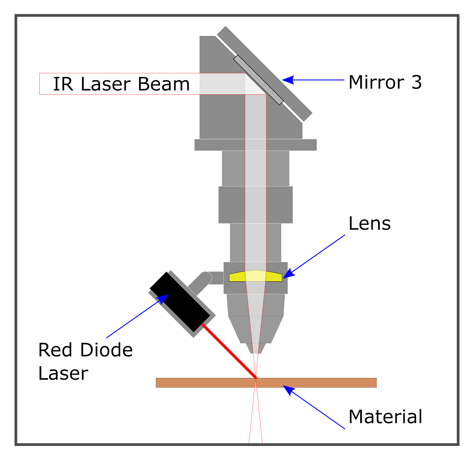
[Martin] explains that there are basically two schools of thought: a head-mounted laser, or a beam combiner. In both cases, a small red diode laser (the kind used in laser pointers) is used to indicate where the primary laser will hit. This allows the user to see exactly what the laser cutter will do when activated, critically important if you’re doing something like engraving a device and only have one chance to get it right. Running a “simulation” with the red laser removes any doubt before firing up the primary laser.

That’s the idea, anyway. In his experience, both methods have their issues. Head-mounted lasers are easier to install and maintain, but their accuracy changes with movement of the machine’s Z-axis: as the head goes up and down, the red laser dot moves horizontally and quickly comes out of alignment. Using the beam combiner method should, in theory, be more accurate, but [Martin] notes he’s had quite a bit of trouble getting both the red and IR lasers to follow the same course through the machine’s mirrors. Not only is it tricky to adjust, but it’s also much more complex to implement and may even rob the laser of power due to the additional optics involved.

In the end, [Martin] doesn’t think there is really a clear winner. Neither method gives 100% accurate results, and both are finicky, though in different scenarios. He suggests you just use whatever method your laser cutter comes with from the factory, as trying to change it probably isn’t worth the effort. But if your machine doesn’t have anything currently, the head-mounted laser is certainly the easier one to retrofit.

In the past, we’ve covered a third and slightly unconventional way of aiming the K40, as well as a general primer for anyone looking to pick up eBay’s favorite laser cutter.

Soyuz Failure Leaves Questions Unanswered

The Russian space program experienced its first serious incident on a manned mission in 35 years when Soyuz MS-10 failed during ascent on October 11th, 2018. The abort system worked as designed, and crew members Aleksey Ovchinin and Nick Hague landed safely approximately 430 km from the launch site in Baikonur. Beyond being put through unusually high G forces, the two men suffered no injuries and will have their mission recycled for a future flight.

From an abort standpoint, the event went as well as could possibly be expected. The fact that the crew walked away unharmed is a testament to the emergency systems on the rocket and spacecraft, and serve as a reminder of why these functions are designed into manned rockets even if they are rarely (if ever) used. The success is especially impressive considering the Soyuz’s launch abort tower, the solid fuel rocket designed to pull the spacecraft away from the failing booster rocket, had already been jettisoned before the event occurred. The spacecraft was instead pulled to safety by the secondary abort thrusters, which were added to the vehicle’s design in 1975 as a contingency and until now had never been used in a real-life scenario.

What Went Wrong?

But while the safe return of the crew was naturally the first priority for all agencies involved, the questions soon turned to the Soyuz itself. What caused the loss of the rocket? Is it a defect which could be present in the other Soyuz rockets currently under construction? Perhaps most importantly, when could the Soyuz fly again? As it’s currently the only way to put humans into space, the International Space Station is completely dependent on regular Soyuz flights, and a delay in the program could endanger the orbiting outpost.

Now, with the initial findings of the Russian incident investigation being made public, we’re starting to get answers on some of those questions. The official report so far agrees with the conclusions many “Armchair Astronauts” made watching the live stream of the launch, and the evidence suggests that the core issue is the same which doomed previous Russian vehicles.

Continue reading “Soyuz Failure Leaves Questions Unanswered”

The Negative Rail Explained

With the high availability of modular components and incredible wealth of information and tutorials online, it’s now easier than ever for hackers and makers to assemble complex electronic projects without getting bogged down with the theory behind it all. But the downside is that the modern electronic hobbyist often doesn’t have as deep an understanding of the low-level concepts that they would have if they had to build everything from scratch. This can be a problem when they try diagnosing and repairing faults, or when they start to branch out into reverse engineering.

Which makes “Building Blocks” by [David Christensen] a very compelling series. Every week he will be demonstrating a new circuit on his blog, complete with a plain English explanation of how and why it’s used. In this first installment of the series, he’s tackling a concept most of us have seen when poking around in more complex electronic devices, but maybe never really gave much thought to: the negative rail.

What exactly is the negative rail, anyway? It’s pretty easy to understand the positive rail in a circuit and its relation to ground; even multiple positive rails, such as in devices which use both 5 V and 3.3 V, are simple enough to wrap your head around. Unfortunately when something drops below that logical 0V reference, it isn’t quite as intuitive. But as [David] explains, the negative rail in a circuit is critical for dealing with bipolar signals, such as audio, which ride above and below the 0 V center point.

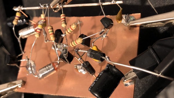
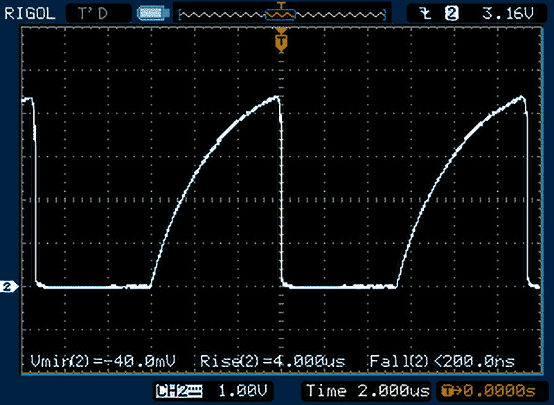
[David] goes over a few methods used to create the negative rail, from the classic center-tap transformer to using a buck-boost converter. But not content with just describing how these circuits work, he walks the reader through the creation of a charge pump circuit that you can drop into your next project if you find yourself in need of the elusive voltage. After explaining and diagramming it, he builds the circuit on a scrap piece of copper clad board and puts it through some benchmarks to prove it matches the theory he laid out.

If you’re in the mood for more negative talk, check out the battle our very own [Steven Dufresne] had with voltages of varying polarity when building his BB-8 robot.

Pringles Can Turned Vaporwave Lamp

We play host to a lot of incredibly complex projects here at Hackaday; take a look at some of the entries in the Hackaday Prize for some real world-class engineering. But the hacks you can knock out in an afternoon are often just as compelling as the flagship projects. After all, not everyone is looking to devote years of their lives into building some complex machine.

Case in point, this very slick lamp built by [mytzusky]. Made of nothing more exotic than an old Pringles can and an RGB LED strip, this is something that can potentially be built with what you have laying around right now. All you need to provide is a bit of geometry, a steady hand, and a love for anything that looks like it could pass as a prop in a TRON fan film.

The first step is getting the Pringles can: either find one in the trash or treat yourself to a stack of weird hard potato chip sorta things. Once you’ve got the can, you need to cut out your design. You could print out the template provided by [mytzusky] if you want, but you could put your own spin on it instead. Just remember that the design needs to make sense when you wrap it around the can.

With the lines cut out of the can, the whole thing gets wrapped with a few sheets of standard white paper. This will not only cover the original label but diffuse the light coming from the cuts you’ve just made. [Mytzusky] doesn’t mention it, but some kind of sealer applied to the paper might be a good idea if you’re looking to keep this thing around for the long haul.

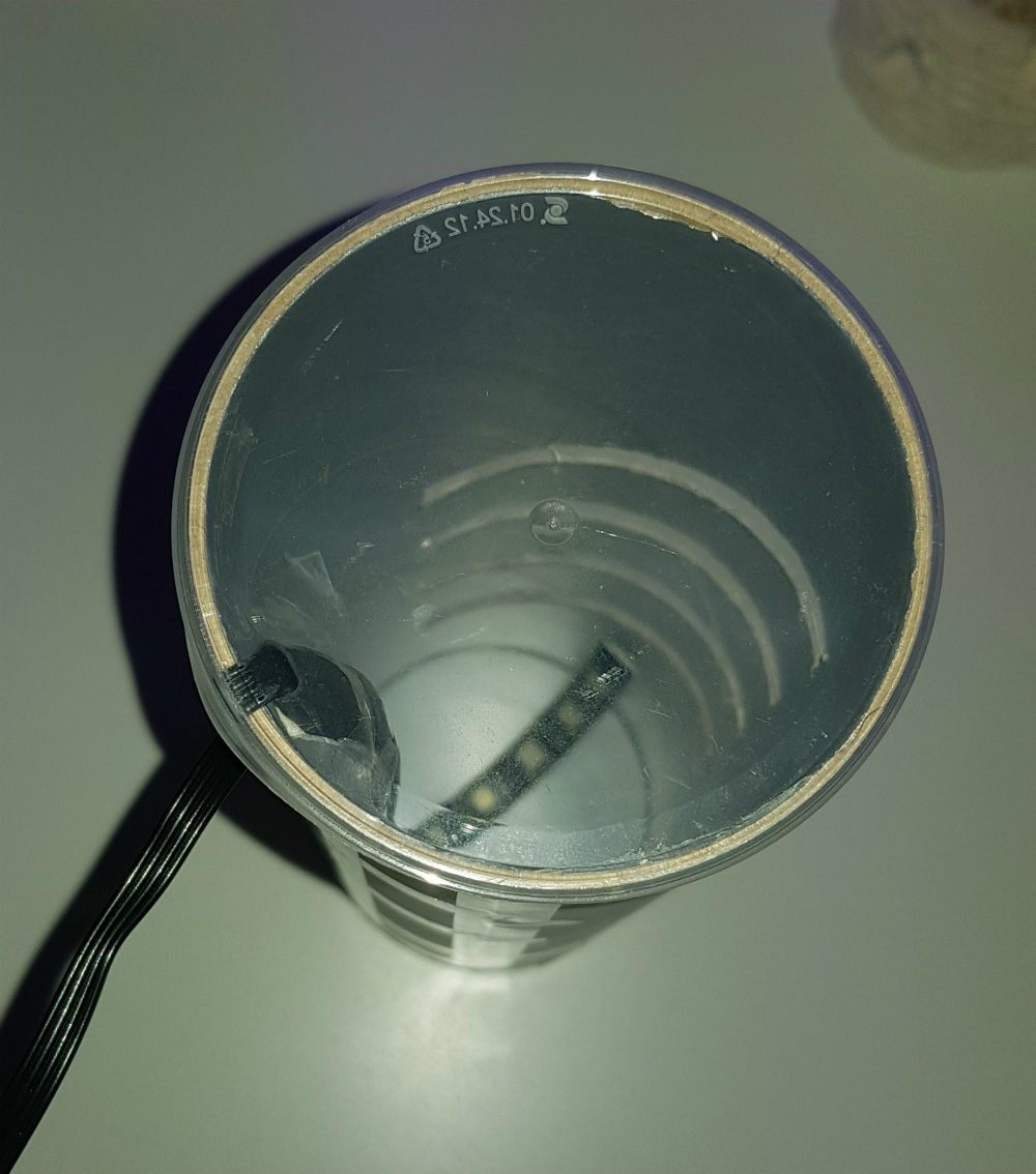
Finally, an RGB LED strip goes inside the can. Make sure to flip the can upside down for this part, with the solid end on the top and the clear lid on the bottom. Not only does this let you run the wire out of the bottom, but provides a very cool ring of diffuse light at the bottom of the lamp.

This is another excellent example of an “upcycled” project which uses literal trash as a building material. It might take a little outside the box thinking, but the results can be very impressive.