Stars Looking A Bit Dim? Throw Some Math At Them.

As the cost of high-resolution images sensors gets lower, and the availability of small and cheap single board computers skyrockets, we are starting to see more astrophotography projects than ever before. When you can put a $5 Raspberry Pi Zero and a decent webcam outside in a box to take autonomous pictures of the sky all night, why not give it a shot? But in doing so, many hackers are recognizing a fact well-known to traditional telescope jockeys: seeing a few stars is easy, seeing a lot of stars is another story entirely.

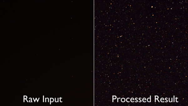
The problem is that stars are fairly dim; a problem compounded by the light pollution you get unless you’re out in a rural area. You can’t just brighten up the images either, as that only increases the noise in the image. A programmer always in search of a challenge, [Benedikt Bitterli] decided to take a shot at using software to improve astrophotography images. He documented the entire process, failures and all, on his blog for anyone else who might be curious about what it really takes to create the incredible images of the night sky we see in textbooks.

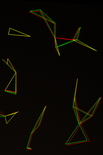
In principle it’s simple: just take a lot of pictures of the sky, stack them on top of each other, and identify which points of light are stars and which ones are noise artifacts. But of course the execution is considerably more difficult. For one thing, unless the camera was on a mount that was automatically tracking the sky, the stars will have slightly moved in each image. To help with this process, [Benedikt] used a navigational trick that humanity has relied on for millennia: mapping constellations. By comparing groupings of stars in each image, his software is able to accurately overlay each image.

But that’s only one part of the equation. In his post, [Benedikt] goes over the incredible amount of math that goes into identifying individual stars in the sea of noise you get when a digital image sensor looks into the black. You certainly don’t need to understand all the math to appreciate the final results, but it’s a fascinating read for those with an interest in computer vision concepts.

This kind of software is precisely what you want to pair with your 3D printed star tracker, or even better a Raspberry Pi sky monitoring station.

[Thanks to Helio Machado for the tip.]

Illuminated Bread For A Cookie Cutter World

Just in case you thought your eyes were playing tricks on you, we’d like to confirm right from the start that what you are looking at is a loaf of bread with internal LED lighting. Why has this bread been internally lit? We can’t really say. But what we can do is pass on the fascinating process that took an unremarkable piece of stale bread and turned it into an exceptional piece of stale bread.

As demonstrated by [The Maker Monster], working with stale bread is basically like working with wood. Wood that you can dip in soup, granted, but wood nonetheless. The process of electrifying the loaf starts with cutting it down the length on a bandsaw, and then hollowing it out with a rotary tool. This creates a fairly translucent shell that’s basically just crust.

You’re probably wondering how you keep a bread-light from getting moldy, and thankfully [The Maker Monster] does address that issue. The bread shell is completely coated with shellac, which creates a hard protective layer that will not only prevent decay but should give it some added strength. In the video it looks like only one coat is applied, but if we had to guess, a few coats would be necessary to really seal it up. Coating it with epoxy wouldn’t be a terrible idea either.

While the shellac dries on the bread, he gets to work on the lighted base (bet you never imagined you’d read a sentence like that), which is really just a sanded piece of wood with a standard LED strip stuck too it. It’s very understated, but of course the glowing loaf really draws the eye anyway. All that’s left is to glue the bread down to the base, and proudly display your creation at your next dinner party.

We can’t say that an electric ciabatta is in the cards for Hackaday HQ; but we know that baking good bread is a science in itself, and turning the failed attempts into works of art does have a certain appeal to it.

Continue reading “Illuminated Bread For A Cookie Cutter World”

Cracking The Case Of Capcom’s CPS2 Security

We love a good deep-dive on a specialized piece of technology, the more obscure the better. You’re getting a sneak peek into a world that, by rights, you were never meant to know even existed. A handful of people developed the system, and as far as they knew, nobody would ever come through to analyze and investigate it to find out how it all went together. But they didn’t anticipate the tenacity of a curious hacker with time on their hands.

[Eduardo Cruz] has done a phenomenal job of documenting one such system, the anti-piracy mechanisms present in the Capcom CPS2 arcade board. He recently wrote in to tell us he’s posted his third and final entry on the system, this time focusing on figuring out what a mysterious six pin header on the CPS2 board did. Hearing from others that fiddling with this header occasionally caused the CPS2 board to automatically delete the game, he knew it must be something important. Hackaday Protip: If there’s a self-destruct mechanism attached to it, that’s probably the cool part.

He followed the traces from the header connector, identified on the silkscreen as C9, back to a custom Capcom IC labeled DL-1827. After decapping the DL-1827 and putting it under the microscope, [Eduardo] made a pretty surprising discovery: it wasn’t actually doing anything with the signals from the header at all. Once the chip is powered up, it simply acts as a pass-through for those signals, which are redirected to another chip: the DL-1525.

[Eduardo] notes that this deliberate attempt at obfuscating which chips are actually connected to different headers on the board is a classic trick that companies like Capcom would use to try to make it harder to hack into their boards. Once he figured out DL-1525 was what he was really after, he was able to use the information he gleaned from his earlier work to piece together the puzzle.

This particular CPS2 hacking journey only started last March, but [Eduardo] has been investigating the copy protection systems on arcade boards since 2014.

[Thanks to Arduino Enigma for the tip.]

Smart Citizen Opens Eyes And Ears In Barcelona

More often than not, our coverage of projects here at Hackaday tends to be one-off sort of thing. We find something interesting, write it up for our beloved readers, and keep it moving. There’s an unending world of hacks and creations out there, and not a lot of time to cover them all. Still, it’s nice when we occasionally see a project we’ve previously covered “out in the wild” so to speak. A reminder that, while a project’s time on the Hackaday front page might be fleeting, their journey is far from finished.

A perfect example can be found in a recent article posted by the BBC about the battle with noise in Barcelona’s Plaza del Sol. The Plaza is a popular meeting place for tourists and residents alike, with loud parties continuing into the middle of the night, those with homes overlooking the Plaza were struggling to sleep. But to get any changes made, they needed a way to prove to the city council that the noise was beyond reasonable levels.

Enter the Smart Citizen, an open source Arduino-compatible sensor platform developed by Fab Lab Barcelona. We originally covered the Smart Citizen board back in 2013, right after it ran a successful funding campaign on Kickstarter. Armed with the data collected by Smart Citizen sensors deployed around the Plaza, the council has enacted measures to try to quiet things down before midnight.

Today people tend to approach crowdfunded projects with a healthy dose of apprehension, so it’s nice to see validation that they aren’t all flash in the pan ideas. Some of them really do end up making a positive impact, years after the campaign ends.

Of course, we can’t talk about distributed environmental monitoring without mentioning the fantastic work of [Radu Motisan], who’s made it his mission to put advanced sensors in the hands of citizen scientists.

[Thanks to muA for the tip.]

Sonoff Postmortem Finds Bugs, Literally

While nobody is exactly sure on the exact etymology of the term, Thomas Edison mentioned some of his inventions being riddled with “bugs” in a letter he wrote all the way back to 1878. In the context of computers, any loyal Hackaday reader should know Grace Hopper’s infamous account of a moth being caught in an early electromechanical computer’s relays. To this pantheon of troublesome insects, we would humbly summit the story of a Sonoff TH16 switch being destroyed by a lowly ant.

According to [CNX Software], the Sonoff TH16 had been working perfectly for a year and a half before the first signs of trouble. One day the switch wouldn’t respond to commands, and a power cycle didn’t seem to clear the issue. Upon opening up the device to see what had gone amiss, it was clearly apparent something had burned up. But upon closer inspection, it wasn’t a fault with the design or even a shoddy component. It was the product of an overly curious ant who got a lot more than he bargained for.

Consulting the wiring diagram of the Sonoff, it appears this poor ant had the terrible misfortune of touching the pins of a through hole capacitor on the opposite side of the board. Bridging this connection not only gave him a lethal jolt, but apparently caused enough current to surge through a nearby resistor that it went up in smoke.

Now, some might wonder (reasonably so) about the conditions in which this switch was operating. If bugs could climb into it, it’s not unreasonable to assume it wasn’t well protected from the elements. Perhaps damp conditions were to blame for the failure, and the image of the ant “riding the lighting” is nothing more than a coincidence. Maybe. But sometimes you just gotta believe.

Incidentally, if you’d like to learn more about the woman who helped secure “bugs” in the IT lexicon, here’s a good place to start.

Ed Note: If you think you’re having deja vu all over again, we did point to this story in the Sunday Links roundup, but the graphics are just so good we couldn’t resist running it in full.

Pocket-size Pi Zero Desktop Features E-paper Display

[Ramin Assadollahi] uses his Raspberry Pi Zero W as a self-contained mobile desktop, connecting to it over VNC from another computer when he wants to hack away at some code or work on a new project. But he often found himself wishing there was some convenient way of displaying pertinent into right on the device, such as what IP address the Pi Zero had pulled. Then he found the 2.13 inch e-Paper HAT for the Pi Zero from Waveshare, and it all clicked into place.

The final device, which he refers to as the StickPi, combines a Pi Zero W, the Waveshare e-Paper display, and a strip of protoboard featuring a few tactile buttons, all inside of a 3D printed case. To really get the most out of the internal volume of his case, [Ramin] soldered the header pins to the Pi Zero in the middle, allowing him to create a space-saving “sandwich” out of all the components.

With the e-Paper display, [Ramin] now has a way to show information on the device itself without having to connect to it over the network. But thanks to the tactile switches on the back connected to the Pi’s GPIO, he also has six programmable buttons that could do anything he wants.

In the most basic implementation, each button could execute a command or script on the Pi. But [Ramin] has something a little more advanced in mind. In the video after the break, he explains that his next step is going to be working on an actual user interface for the Pi’s e-Paper screen, making use of the roughly gamepad style layout of the rear buttons. A “paged” interface with scrolling options would allow the user to perform all sorts of functions quickly and easily, and we’re looking forward to seeing what he comes up with.

This isn’t the first time we’ve seen somebody try to turn the Pi Zero into a more mobile-friendly platform, and the construction method here actually reminds us of a much smaller version of the Zero Phone.

Continue reading “Pocket-size Pi Zero Desktop Features E-paper Display”

Tesla Model 3 Battery Pack Teardown

The Tesla Model 3 has been available for almost a year now, and hackers and tinkerers all over the world are eager to dig into Elon’s latest ride to see what makes it tick. But while it’s considerably cheaper than the Model S that came before it, the $35,000+ USD price tag on the new Tesla is still a bit too high to buy one just to take it apart. So for budget conscious grease monkeys, the only thing to do is wait until somebody with more money than you crashes one and then buy the wreckage cheaply.

Tesla Model 3 battery monitor board

Which is exactly what electric vehicle connoisseur [Jack Rickard] did. He bought the first wrecked Model 3 he could get his hands on, and proceeded to do a lengthy teardown on what’s arguably the heart and soul of the machine: its 75 kWh battery pack. Along the way he made some interesting discoveries, and gained some insight on to how Tesla has been able to drop the cost of the Model 3 so low compared to their previous vehicles.

On a Tesla, the battery pack is a large flat panel which takes up effectively the entire underside of the vehicle. To remove it, [Jack] and his assistant raise the wreck of the Model 3 up on a standard lift and then drop the battery down with a small lift table. Here the first differences are observed: while the Model S battery was made for rapid swapping (a feature apparently rarely utilized in practice), the battery in the Model 3 battery is obviously intended to be a permanent piece of the car; removing it required taking out a good portion of the interior.

With the battery out of the car and opened up, the biggest change for the Model 3 becomes apparent. The battery pack actually contains the charger, DC-DC converter, and battery management system in one integrated unit. Whereas on the Model S these components were installed in the vehicle itself, on the Model 3, most of the primary electronics are stored in this single module.

That greatly reduces the wiring and complexity of the car, and [Jack] mentions the only significant hardware left inside the Model 3 (beyond the motors) would be the user interface computer in the dashboard. When the communication protocol for this electronics module is reverse engineered, it may end up being exceptionally useful for not only electric vehicle conversions but things like off-grid energy storage.

A little over a year ago we featured a similar teardown for the battery back in the Tesla Model S, as well as the incredible project that built a working car from multiple wrecks.

[Thanks to DarksideDave for the tip.]

Continue reading “Tesla Model 3 Battery Pack Teardown”