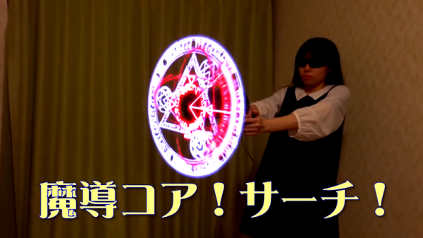
MIT Makes Lego Lab For Microfluidics

As any good hacker (or scientist) knows, sometimes you find the tools you need in unexpected places. For one group of MIT scientists, that place is a box of Lego. Graduate student [Crystal Owens] was looking for new ways to make a cheap, simple microfluidics kit. This technique uses the flow of small amounts of liquid to do things like sort cells, test the purity of liquids and much more. The existing lab tools aren’t cheap, but [Crystal] realized that Lego could do the same thing. By cutting channels into the flat surface of a Lego brick with a precise CNC machine and covering the side of the brick with glass, she was able to create microfluidic tools like mixers, drop makers and others. To create a fluid resistor, she made the channel smaller. To create a larger microfluidic system, she mounted the blocks next to each other so the channels connected. The tiny gap between blocks (about 100 to 500 microns) was dealt with by adding an O-ring to the end of each of channel. Line up several of these bricks, and you have a complete microfluidic system in a few blocks, and a lab that only costs a few dollars.

Continue reading “MIT Makes Lego Lab For Microfluidics”

3D Print A 3D Printer Frame

It is over a decade since the RepRap project was begun, originally to deliver 3D printers that could replicate themselves, in other words ones that could print the parts required to make a new printer identical to themselves. And we’re used to seeing printers of multiple different designs still constructed to some extent on this principle.

The problem with these printers from a purist replicating perspective though is that there are always frame parts that must be made using other materials rather than through the 3D printer. Their frames have been variously threaded rod, lasercut sheet, or aluminium extrusion, leaving only the fittings to be printed. Thus [Chip Jones]’ Thingiverse post of an entirely 3D printed printer frame using a 3D printed copy of aluminium extrusion raises the interesting prospect of a printer with a much greater self-replicating capability. It uses the parts from an Anet A8 clone of a Prusa i3, upon which it will be interesting to see whether the 3D printed frame lends the required rigidity.

There is a question as to whether an inexpensive clone printer makes for the most promising collection of mechanical parts upon which to start, but we look forward to seeing this frame and its further derivatives in the wild. Meanwhile this is not the most self-replicating printer we’ve featured, that one we covered in 2015.

Thanks [MarkF] for the tip.

Here’s Why Hoverboard Motors Might Belong In Robots

[madcowswe] starts by pointing out that the entire premise of ODrive (an open-source brushless motor driver board) is to make use of inexpensive brushless motors in industrial-type applications. This usually means using hobby electric aircraft motors, but robotic applications sometimes need more torque than those motors can provide. Adding a gearbox is one option, but there is another: so-called “hoverboard” motors are common and offer a frankly outstanding torque-to-price ratio.

A teardown showed that the necessary mechanical and electrical interfacing look to be worth a try, so prototyping has begun. These motors are really designed for spinning a tire on the ground instead of driving other loads, but [madcowswe] believes that by adding an encoder and the right fixtures, these motors could form the basis of an excellent robot arm. The ODrive project was a contender for the 2016 Hackaday Prize and we can’t wait to see where this ends up.

A Wrencher On Your Oscilloscope

We like oscilloscope art here at Hackaday, so it was natural to recently feature a Javascript based oscilloscope art generator on these pages, along with its companion clock. Open a web page, scribble on the screen, see it on the ‘scope.

As part of our coverage we laid down the challenge: “If any of you would like to take this further and make a Javascript oscilloscope Wrencher, we’d love to make it famous“. Which of course someone immediately did, and that someone was [Ted] with this JSFiddle. Hook up your soundcard’s left and right to X and Y respectively, press the “logo” button in the bottom right hand pane, fiddle with your voltages and trigger levels for a bit, and you should see a Wrencher on the screen. We’re as good as our word, so here we are making the code famous. Thanks, [Ted]!

It’s not an entirely perfect Wrencher generator, as it has a lot of points to draw in the time available, resulting in a flickery Wrencher. (Update: take a look at the comments below, where he has posted an improved JSFiddle and advice on getting a better screen grab.) Thus the screen shot is an imperfect photograph rather than the usual grab to disk, for some reason the Rigol 1054z doesn’t allow the persistence to be turned up in X-Y mode so each grab only had a small part of the whole. But it draws a Wrencher on the screen, so we’re pretty impressed.

The piece that inspired this Wrencher can be found here. If you think you can draw one with a faster refresh rate, get coding and put it in the comments. We can’t promise individual coverage for each effort though, we’re Hackaday rather than Yet-another-scope-Wrencher-aday.

Repairs You Can Print: 3D Printing Is For (Solder) Suckers

[Joey] was about to desolder something when the unthinkable happened: his iconic blue anodized aluminium desoldering pump was nowhere to be found. Months before, having burned himself on copper braid, he’d sworn off the stuff and sold it all for scrap. He scratched uselessly at a solder joint with a fingernail and thought to himself: if only I’d used the scrap proceeds to buy a backup desoldering pump.

Determined to desolder by any means necessary, [Joey] dove into his junk bin and emerged carrying an old pump with a broken button. He’d heard all about our Repairs You Can Print contest and got to work designing a replacement in two parts. The new button goes all the way through the pump and is held in check with a rubber band, which sits in a groove on the back side. The second piece is a collar with a pair of ears that fits around the tube and anchors the button and the rubber band. It’s working well so far, and you can see it suck in real-time after the break.

We’re not sure what will happen when the rubber band fails. If [Joey] doesn’t have another, maybe he can print a new one out of Ninjaflex, or build his own desoldering station. Or maybe he’ll turn to the fire and tweezers method.

Continue reading “Repairs You Can Print: 3D Printing Is For (Solder) Suckers”

Careful Testing Reveals USB Cable Duds

What’s worse than powering up your latest build for the first time only to have absolutely nothing happen? OK, maybe it’s not as bad as releasing the Magic Smoke, but it’s still pretty bewildering to have none of your blinky lights blink like they’re supposed to.

What you do at that point is largely a matter of your troubleshooting style, and when [Scott M. Baker]’s Raspberry Pi jukebox build failed to chooch, he returned to first principles and checked the power cable. That turned out to be the culprit, but instead of giving up there, he did a thorough series of load tests on multiple USB cables to see which ones were suspect, with interesting results.

[Scott] originally used a cable with a USB-A on one end and a 3.5-mm barrel plug on the other with a switch in between, under the assumption that the plug on the Pi end would be more robust, as well as to have a power switch for the jukebox. Testing that cable using an adjustable DC load would prove that the cable was unfit for Pi duty, dropping the voltage to under 2 volts at a measly 500-mA load. Other cables proved much better under load, even those with USB mini jacks and even one with a 5.5-mm barrel. But the larger barrel-plug cable also proved to be a stinker when it was paired with an inline switch. In the video below, [Scott] walks through not only the testing process, but also gives a quick tour of his homebrew DC load.

The lesson is clear: not all USB cables are created equal, so caveat hacker. And if you’ve got a yen to check the cables in your junk bin like [Scott] did, this full-featured smart DC load might be just the thing.

Continue reading “Careful Testing Reveals USB Cable Duds”

You Can Learn A Lot From A Blinkenrocket

At this year’s Chaos Communication Congress, we caught up with [muzy] and [overflo], who were there with a badge and soldering project they designed to teach young folks how to solder and program. Blinkenrocket is a basically a 64-LED matrix display and just enough support hardware to store and display animations, and judging by the number of blinking rockets we saw around the necks of attendees, it was a success.

Their talk at 34C3 mostly concerns the production details, design refinements, and the pitfalls of producing thousands of a thing. If you’re thinking of building a hardware kit or badge on this scale, you should really check it out and crib some of their production optimization tricks.

For instance, instead of labelling the parts “C2” or “R: 220 Ohms”, they used a simple color-coding scheme. This not only makes it easier for kids to assemble, but it also means that they didn’t have to stick 1,000 part labels on every component. Coupled with [overflo]’s Zerhacker, SMD parts in strips were cut to the right length and color-coded in one step, done by machine.

The coolest feature of the Blinkenrocket itself is the audio programming interface. It’s like in the bad old days of software stored on cassette tapes, but it’s a phenomenal interface for getting a simple animation out of a web app and straight into a piece of minimal hardware — just plug it into a laptop or cell phone’s audio out and press “play” in the browser. The original design tried to encode the data in the pulse-length of square waves, but this turned out to be very hardware dependent. The final design used frequency-shift keying. What’s old is new again.

Everything you could want to know about the design, its code, and even the website itself are up on the project’s GitHub page, so go check it out. If you’d like to arrange a Blinkenrocket workshop yourself, shoot [muzy] or [overflo] an e-mail. Full disclosure: [overflo] gave us a kit, the “hard-mode” SMD one with 0805 1206 parts, and it was fun to assemble and program.