Toaster Oven Reflow Controllers

With a lot of people who are suddenly too cool for through hole and of course the a few generations of components that are only available in SMD packages, it’s no surprise the humble toaster oven has become one of the mainstays of electronic prototyping. You’re gonna need a controller to ramp up those temperatures, so here are two that do the job quite nicely.

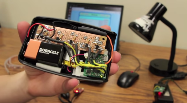
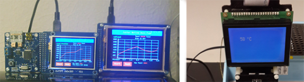
[Nathan]’s Zallus Oven Controller is a bit different than other reflow controllers we’ve seen on Kickstarter. He’s offering three versions, two with different sized touch screen displays, and one that is controlled with a PC and push buttons. The display for these is beautiful, and of course you can program your own temperature profiles.

If Kickstarter isn’t your thing, [Dirk] created his own reflow controller. Like the Zallus, this has a graphical display, but its homebrew lineage means it should be simpler to maintain. It uses a K-type thermocouple, and unlike every other reflow controller we’ve ever seen, [Dirk] is actually checking the accuracy of his temperature probe.

No, reflow oven controllers aren’t new, and they aren’t very exciting. They are, however, tools to build much cooler stuff, and a great addition to any lab.
PCB Drill Microscope

PCB Drill Press Gets A Microscopic Upgrade

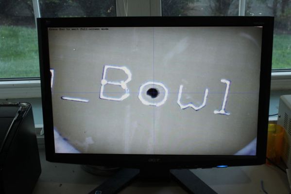
If you get into more complicated PCB design, you’ll find the need to drill tiny and accurate holes much more often. Wouldn’t it be nice to have a precise way of doing that? Maybe even something as simple as strapping a $10 USB digital microscope to it?

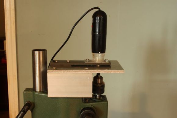
That was [mlerman’s] thought anyway, and from the looks of it, it seems to work quite well! If you already have a PCB drill press then it’s just a matter of installing the microscope opposite the drill — align it to the center point with some cross hairs and boom you’re in business.

But if you don’t yet have a PCB drill, [mlerman’s] got you covered there too, as he explains in great detail how to modify a cheap drill press into an inverted PCB drill press.

Inverted PCB Drill Press

Wait, why is it inverted? Besides making more room for the USB microscope to sit, it also ensures the microscope lens doesn’t get covered in the PCB fairy dust that would fall on it if it were in a normal orientation.

[via Embedded-Lab]

Hackaday 10th Anniversary: Wrap-up

A little more than a month ago we saw the 10 year anniversary of the first Hackaday post ever, and last week we had a little get together in Pasadena to celebrate the occasion. Everyone had a great time, building tiny line-following robots and LiPo chargers, listening to some great talks, and in the evening we all had a lot of fun emptying some kegs. We couldn’t ask for a better crowd, and we thank everyone who came (and those of you who watched everything on the livestream) for participating.
As far as specific people go, we need to thank [charliex], [arko] and everyone else from Null Space Labs for helping out with the weird rotary encoder two-player version of Duck Hunt. The folks from Crashspace were also there, helping out and lending a steady hand and hot soldering iron during the workshops. Shoutouts also go to [datagram] and [jon king] for running the lockpicking workshop, and [Todd Black] deserves a mention for his lithium battery charger workshop. All the speakers deserve to be mentioned again, and you can check out a playlist of their talks below:

Continue reading “Hackaday 10th Anniversary: Wrap-up”

camera dolly

Timelapse Photography On An Android-Powered Dolly

If you’re heading off on a trip to Alaska, you need to make sure you have plenty of supplies on hand for the wilderness that awaits. If you’re [Bryce], that supply list includes some interesting photography equipment, including a camera dolly that he made to take time-lapse video of the fantastic scenery.

On the hardware side, the dolly carries the camera on a rail that is set up on a slant. The camera starts on one side and moves up and towards the otherside which creates a unique effect in the time-lapse. The rig is driven by a stepper motor, and rides on some pretty fancy bearings. The two cameras [Bryce] plans to use are a Canon T2i and a EOS-M which sit on the top from a tripod.

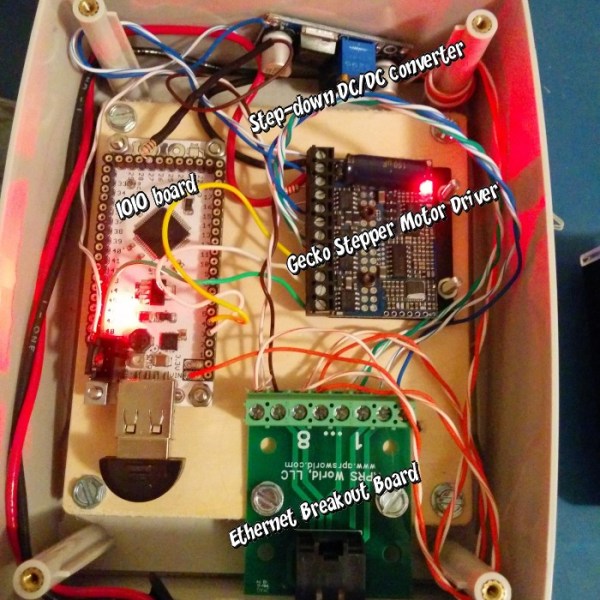
The software and electronics side is interesting as well. Instead of the usual Arduino, [Bryce] opted for controlling the rig through Android and a IOIO board. This gives the project a lot of options for communications, including Bluetooth. The whole thing is powered by a 19V battery pack. If you’re looking for something a little simpler, you might want to check out the egg timer for time lapse! Check out the video of [Bryce]’s rig in action after the break.

Continue reading “Timelapse Photography On An Android-Powered Dolly”

Home Automation

Home Automation With A Custom Wireless Sensor Network

We’re no strangers to home automation projects around here, but it’s not often that you see one described in this much detail. [Paul] designed a custom home automation system with four teammates for an undergraduate thesis project.

The system is broken into two main components; the server and the peripherals. The team designed their peripherals from early prototypes of an upcoming ArduIMU v4 measurement unit. They removed all of the default sensors to keep costs down and reduce assembly time. The units can them be hooked up to various peripherals such as temperature sensors, mains relays, RGB color strips, etc.

The central management of the system is performed using a web-based user interface. The web server runs on Java, and interacts with the peripherals wirelessly. Basic messages can be sent back and forth to either read the state of the peripherals or to change the state. As far as the user is concerned, these messages appear as simple triggers and actions. This makes it very simple to program the peripherals using if, then, else logic.

The main project page is a very brief summary of what appears to be a very well documented project. The team has made available their 182 page final report (pdf), which goes into the nitty-gritty details of the project. Also, be sure to watch the demonstration video below. Continue reading “Home Automation With A Custom Wireless Sensor Network”

DIY Optoisolator

MacGyvered Optoisolator Is A Great Introduction

Sometimes the best way to learn about a technology is to just build something yourself. That’s what [Dan] did with his DIY optoisolator. The purpose of an optoisolator is to allow two electrical systems to communicate with each other without being electrically connected. Many times this is done to prevent noise from one circuit from bleeding over into another.

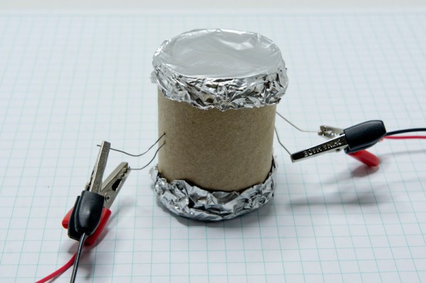
[Dan] built his incredibly simple optoisolator using just a toilet paper tube, some aluminum foil, an LED, and a photo cell. The electrical components are mounted inside of the tube and the ends of the tube are sealed with foil. That’s all there is to it. To test the circuit, he configured an Arduino to send PWM signals to the LED inside the tube at various pulse widths. He then measured the resistance on the other side and graphed the resulting data. The result is a curve that shows the LED affects the sensor pretty drastically at first, but then gets less and less effective as the frequency of the signal increases.

[Dan] then had some more fun with his project by testing it on a simple temperature controller circuit. An Arduino reads a temperature sensor and if the temperature rises above a certain value, it turns on a fan to cool the sensor off again. [Dan] first graphed the sensor data with no fan hooked up. He only used ambient air to cool things down. The resulting graph is a pretty smooth curve. Next he hooked the fan up and tried again. This time the graph went all kinds of crazy. Every time the fan turned on, it created a bunch of electrical noise that prevented the Arduino from getting an accurate analog reading of the temperature sensor.

The third test was to remove the motor circuit and move it to its own bread board. The only thing connecting the Arduino circuit to the fan was a wire for the PWM signal and also a common ground. This smoothed out the graph but it was still a bit… lumpy. The final test was to isolate the fan circuit from the temperature sensor and see if it helped the situation. [Dan] hooked up his optoisolator and tried again. This time the graph was nice and smooth, just like the original graph.

While this technology is certainly not new or exciting, it’s always great to see someone learning by doing. What’s more is [Dan] has made all of his schematics and code readily available so others can try the same experiment and learn it for themselves.

Ask Hackaday: Who Is Going To Build This Pneumatic Transmission Thing?

fluid_transmission

Disney research is doing what they do best, building really cool stuff for Disney and telling the rest of the world how cool they are. This time, it’s a very low friction fluid transmission device designed for animatronics.

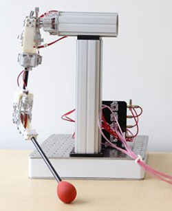
From testing a few toy robotic arms, we can say without a doubt that servos and motors are not the way to go if you’re designing robots and animatronics that need lifelike motion. To fix this, a few researchers at Disney Pittsburgh have turned to pneumatics and hydraulics, where one joint is controlled by two sets of pistons. It’s extremely similar to the pneumatic LEGO, but more precise and much more lifelike.

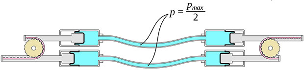
The system uses a pair of cylinders on each joint of a robot. Disney is using a rolling diaphragm to seal the working fluid in its tubes and cylinders. This is an extremely low-friction device without any shakiness or jitters found with simple o-ring pneumatics and hydraulics.

The system is backdriveable, meaning one robotic arm can control another, and the other way around. Since we’re dealing with hydraulics, the cylinders (and robotic/animatronic devices) don’t need to be the same size; a small device could easily control a larger copy of itself, and vice versa.

The devices are fairly simple, with gears, toothed belts, and bits of plastic between them. The only unique part of these robots is the rolling diaphragm, and we have no idea where to source this. It looks like it would be great for some robotics or an Iron Man-esque mech suit, but being able to source the components will be a challenge.

You can check out the videos of these devices below, and if you have any idea on how to build your own, leave a note in the comments.

Continue reading “Ask Hackaday: Who Is Going To Build This Pneumatic Transmission Thing?”