3D Printed Dump Truck Carries Teeny Loads

What do you do when you already have a neat little radio-controlled skid-steer loader? Well, if you’re [ProfessorBoots], you build a neat little dump truck to match!

The dump truck is built out of 3D printed components, and has proportions akin to a heavy-duty mining hauler. The dump bed and wheels were oversized relative to the rest of the body to give it a more cartoonish look.

An ESP32 is the brains of the operation. The build is powered by a nifty little 3.6 V rechargeable lithium-ion battery with an integral Micro USB charge port. It’s paired with a boost converter to provide a higher voltage for the servos and motors. Drive is to the rear wheels, thanks to a small DC gear motor. Unlike previous skid-steer designs from [ProfessorBoots], this truck has proper servo-controlled steering. The printed tires are wrapped in rubber o-rings, which is a neat way to make wheels that grip without a lot of fuss. The truck also has a fully-functional dump bed, which looks great fun to play with.

The final build pairs great with the loader that [ProfessorBoots] built previously.

Continue reading “3D Printed Dump Truck Carries Teeny Loads”

USB-C For Hackers: Build Your Own PSU

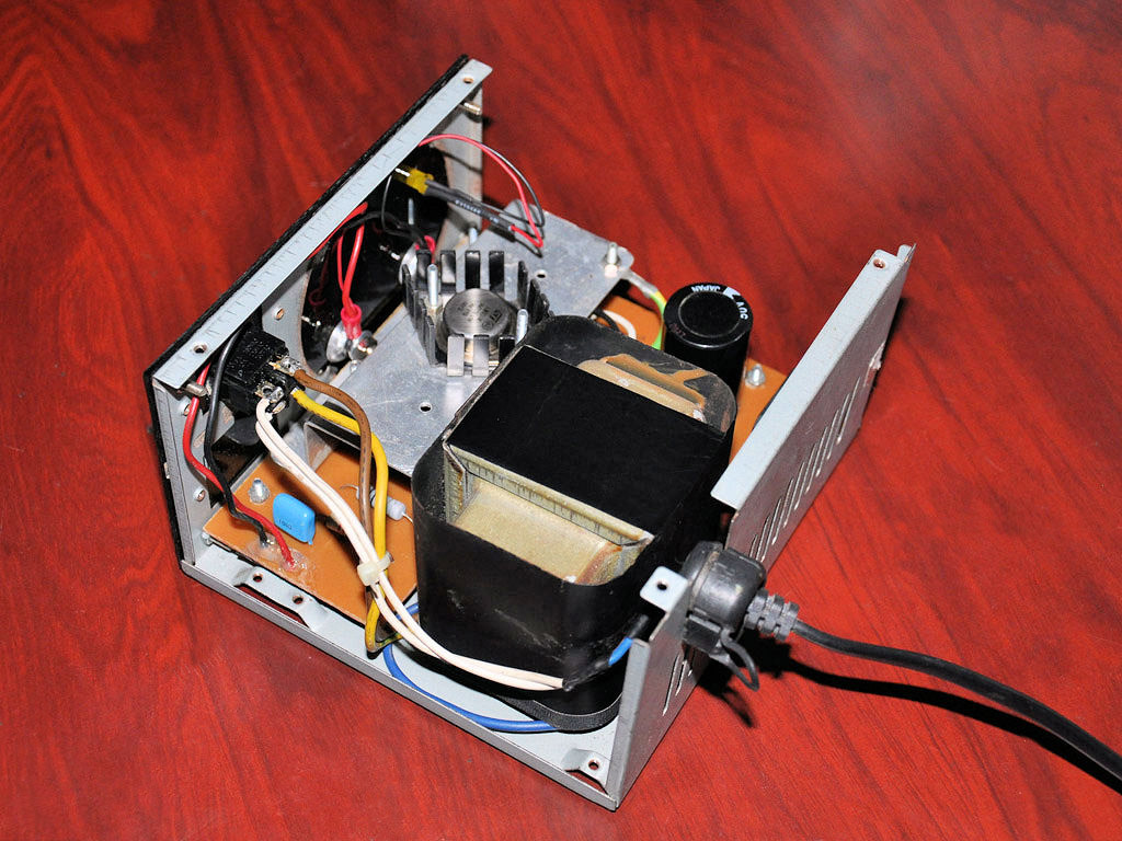
What if you wanted to build your own USB-C PSU? Good news – it’s easy enough! If you ever wanted to retrofit a decent DC PSU of yours to the USB-C standard, say, you got a Lenovo/HP/Dell 19V-20V charger brick and you’ve ever wished it were USB-C, today is the day when we do exactly that. To be fair, we will cheat a bit – but only a tiny bit, we won’t be deviating too much from the specification! And, to begin with, I’ll show you some exceptionally easy ways that you can turn your DC PSU into a USB-C compatible one, with a simple module or a few.

Turning a 20 V PSU into a USB-C PSU feels natural if you want to charge a laptop – those tend to request 20 V from a USB-C PSU anyway, so what’s the big deal? However, you can’t just put 20 V onto a USB-C connector – you have to add a fair bit of extra logic to make your newly christened USB-C PSU safe to use with 5 V devices, and this logic also requires you go through a few extra steps before 20 V appears on VBUS. Any USB-C PSU has to output 5 V first and foremost whenever a device is connected, up until a higher voltage is negotiated digitally, and the PSU may only switch to a higher voltage output when it’s requested to do so.

Now, for that, a PSU offers a list of profiles, and we looked into those profiles in the Replying PD article – each profile is four bytes that contain information about the profile voltage, maximum current that the device may draw at that voltage, and a few other details. For a PSU to be USB-C compliant, the USB-C specification says that, in addition to 5 V, you may also offer 9 V, 15 V, and 20 V.

Also, the specification says that if a PSU supports certain in-spec voltage like 15 V, it’s also required by the spec to offer all of the spec-defined voltages below the maximum one – for 15 V, that also requires supporting 9 V. Both of these are UX requirements, as opposed to technical requirements – it’s easier for device and PSU manufacturers to work with a small set of pre-defined voltages that majority of the chargers will support, but in reality, you can actually offer any voltage you want in the PSU advertisement; at worst, a device is going to refuse and contend with slowly charging from the 5 V output that you’re required to produce.

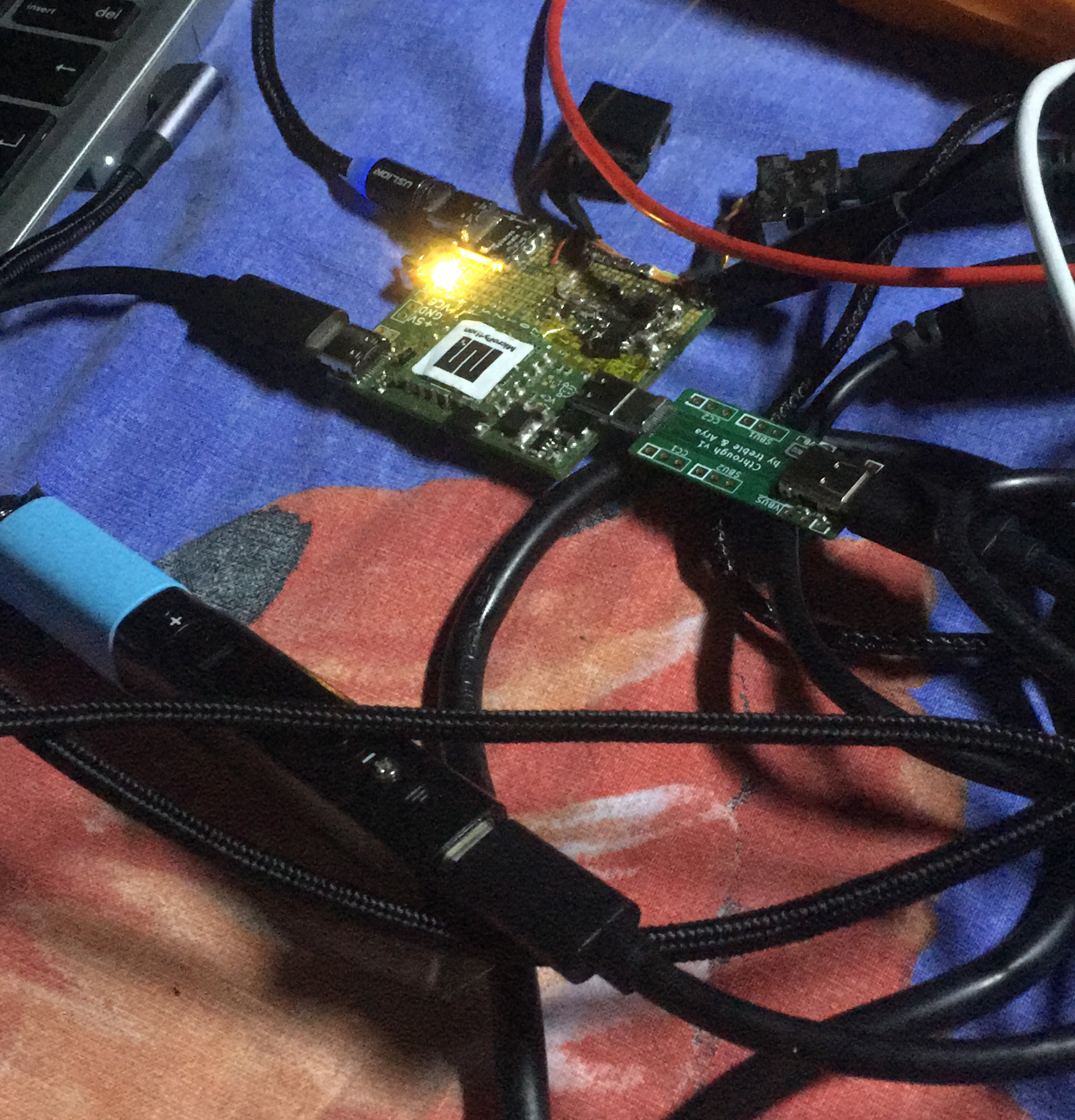
I’d like to walk you through how off-the-shelf USB-C PSUs work, all of the options you can use to to create one, and then, let’s build our own USB-C PSU from scratch! Continue reading “USB-C For Hackers: Build Your Own PSU”

A Pulse Of Annoyance About Oscillators, Followed By A Flyback Of A Rant

Everyone likes to play with high voltages, right?. Even though the danger of death goes up with every volt, it’s likely that a few readers will have at some time or other made fancy long sparks. You’re reading this so you lived to tell the tale, and we’d only ever counsel only doing so safely, but the point of this piece lies not in the volts themselves but in a touch of frustration at the voltage generators. There’s a circuit I see so often which annoys me every single time, so here if you don’t mind I’m going to deliver both a little rant and a look into flyback converters.

It’s Got Coils, so It’s A Transformer

A power supply with the lid removed, visible is a large transformer
Linear power supplies with a mains transformer are a surprisingly rare sight now. Dilshan Jayakody, CC BY-SA 2.0.

How does a transformer work? An alternating current in a primary winding induces an opposite current in its secondary winding. The voltage out is equal to the turns ratio times the voltage in. Thus if you want to make a high voltage, it’s simply a case of finding a transformer with the right turns ratio, and applying the right AC to the input.

A handy choice for a high voltage transformer has been for years a TV line output transformer, also sometimes known as a flyback transformer. You could find these in CRT displays and TVs, and they consist of a square ferrite core with a big chunky high voltage overwinding for the CRT anode circuit and a load of lower voltage windings. TV designers were always out to save on parts costs, so they often had windings for all the voltage rails inside the set as well as the anode voltage, using the timebase as a crude switching power supply. Continue reading “A Pulse Of Annoyance About Oscillators, Followed By A Flyback Of A Rant”

Minimizing Stress On A Coin Cell Battery

When it comes to powering tiny devices for a long time, coin cell batteries are the battery of choice for things like keyfobs, watches, and even some IoT devices. They’re inexpensive and compact and a great choice for very small electricity needs. Their major downside is that they have a relatively high internal resistance, meaning they can’t supply a lot of current for very long without decreasing the lifespan of the battery. This new integrated circuit uses a special DC-DC converter to get over that hurdle and extend the life of a coin cell significantly.

A typical DC-DC converter uses a rapidly switching transistor to regulate the energy flow through an inductor and capacitor, effectively stepping up or stepping down the voltage. Rather than relying on a single converter, this circuit uses a two-stage system. The first is a boost converter to step the voltage from the coin cell up to as much as 11 volts to charge a storage capacitor. The second is a buck converter which steps that voltage down when there is a high current demand. This causes less overall voltage drop on the battery meaning less stress for it and a longer operating life in the device.

There are a few other features of this circuit as well, including an optimizer which watches the behavior of the circuit and learns about the power demands being placed on it. That way, the storage capacitor is only charged up to its maximum capacity if the optimizer determines that much charge is needed. With all of these features a coin cell could last around seven times as long as one using more traditional circuitry. If you really need to get every last bit of energy from a battery, though, you can always use a joule thief.

Review: Beepy, A Palm-sized Linux Hacking Playground

In the long ago times, when phones still flipped and modems sang proudly the songs of their people, I sent away for a set of Slackware CDs and embarked on a most remarkable journey. Back then, running Linux (especially on the desktop) was not a task to be taken lightly. The kernel itself was still in considerable flux — instead of changing some obscure subsystem or adding support for a niche gadget you don’t even own, new releases were unlocking critical capabilities and whole categories of peripherals. I still remember deciding if I wanted to play it safe and stick with my current kernel, or take a chance on compiling the latest version to check out this new “USB Mass Storage” thing everyone on the forums was talking about…

But modern desktop Linux has reached an incredible level of majority, and is now a viable choice for a great number of computer users. In fact, if you add Android and Chrome OS into the mix, there are millions and millions of people who are using Linux on daily basis and don’t even realize it. These days, the only way to experience that sense of adventure and wonderment that once came pre-loaded with a Linux box is to go out and seek it.

Which is precisely how it feels using using the Beepy from SQFMI. The handheld device, which was formerly known as the Beepberry before its creators received an all-too-predicable formal complaint, is unabashedly designed for Linux nerds. Over the last couple of weeks playing with this first-run hardware, I’ve been compiling kernel drivers, writing custom scripts, and trying (though not always successfully) to get new software installed on it. If you’re into hacking around on Linux, it’s an absolute blast.

There’s a good chance that you already know if the Beepy is for you or not, but if you’re still on the fence, hopefully this in-depth look at the hardware and current state of the overall project can help you decide before SQFMI officially starts taking new orders for the $79 gadget.

Continue reading “Review: Beepy, A Palm-sized Linux Hacking Playground”

A loudspeaker with a supercapacitor PCB next to it

Hackaday Prize 2023: Supercapacitors Let Solar Speaker Work In Darkness

Solar panels are a great way to generate clean electricity, but require some energy storage mechanism if you also want to use their power at night. This can be a bit tricky for large solar farms that feed into the grid, which require enormous battery banks or pumped storage systems to capture a reasonable amount of energy. It’s much easier for small, handheld solar gadgets, which work just fine with a small rechargeable battery or even a big capacitor. [Jamie Matthews], for instance, built a loudspeaker that runs on solar power but can also work in the dark thanks to two supercapacitors.

The speaker’s 3D-printed case has a 60 x 90 mm2 solar panel mounted at the front, which charges a pair of 400 Farad supercaps. Audio input is either through a classic 3.5 mm socket or through the analog audio feature of a USB-C socket. That same USB port can also be used to directly charge the supercaps when no sunlight is available, or to attach a Bluetooth audio receiver, which in that case will be powered by the speaker.

A speaker's passive radiator next to a solar panel
The solar panel sits right next to the passive radiator before both are covered with speaker fabric.

The speaker’s outer shell, the front bezel, and even the passive radiator are 3D-printed and spray-painted. The radiator is made of a center cap that is weighed down by a couple of M4 screws and suspended in a flexible membrane. [Jamie] used glue on all openings to ensure the box remains nearly airtight, which is required for the passive radiator to work properly. Speaker fabric is used to cover the front, including the solar panel – it’s apparently transparent enough to let a few watts of solar power through.

A salvaged three-inch Bose driver is the actual audio source. It’s driven by a TI TPA2013D1 chip, which is a 2.7 W class-D amplifier with an integrated boost converter. This enables the chip to keep a constant output power level across a wide supply voltage range – ideal for supercapacitor operation since supercaps don’t keep a constant voltage like lithium batteries do.

[Jamie] has used the speaker for more than nine months so far and has only had to charge it twice manually. It probably helps that he lives in sunny South Africa, but we’ve seen similar solar audio projects work just fine in places like Denmark. If you’re taking your boombox to the beach, a sunscreen reminder feature might also come in handy.

A black work mat holds a circular badge with 64 addressable LEDs in a spiraling shape akin to the center of a sunflower. The LEDs have a rotating rainbow spiraling around the circle with red touching violet on one end. The colors extend in bands from the center to the rim of the circle.

Math You Can Wear: Fibonacci Spiral LED Badge

Fibonacci numbers are seen in the natural structures of various plants, such as the florets in sunflower heads, areoles on cacti stems, and scales in pine cones. [HackerBox] has developed a Fibonacci Spiral LED Badge to bring this natural phenomenon to your electronics.

To position each of the 64 addressable LEDs within the PCB layout, [HackerBox] computed the polar (r,θ) coordinates in a spreadsheet according to the Vogel model and then converted them to rectangular (x,y) coordinates. A little more math translates the points “off origin” into the center of the PCB space and scale them out to keep the first two 5 mm LEDs from overlapping. Finally, the LED coordinates were pasted into the KiCad PCB design file.

An RP2040 microcontroller controls the show, and a switch on the badge selects power between USB and three AA batteries and a DC/DC boost converter. The PCB also features two capacitive touch pads. [HackerBox] has published the KiCad files for the badge, and the CircuitPython firmware is shared with the project. If C/C++ is more your preference, the RP2040 MCU can also be programmed using the Arduino IDE.

For more details on beautiful RGB lights, we’ve previously presented Everything You Might Have Missed About Addressable LEDs, and for more details on why they can be so fun to wear, check out our Hackaday Badgelife Documentary.

(Editor’s note: HackerBox makes and sells kits, is run by Hackaday Contributor [Joseph Long] IRL.)

Continue reading “Math You Can Wear: Fibonacci Spiral LED Badge”