If you want to visualize sound waves, you reach for your oscilloscope, right? That wasn’t an option in 1905 so physicist [Heinrich Rubens] came up with another way involving flames. [Luke Guigliano] and [Will Peterson] built one of these tubes — known as a Rubens’ tube — and will show you how you can, too. You can see a video of their results, below. Just in case a flame oscilloscope isn’t enough to attract your interest, they are driving the thing with a theremin for extra nerd points.
The guys show a short flame run and one with tall flames. The results are surprising, especially with the short flames. Of course, the time base is the length of the tube, so that limits your measurements. The tube has many gas jets along the length and with a sound source, the height of the flames correspond to the air pressure from the sound inside the tube.
The story goes that Atari was developing a premium model of their popular home video game console, the Atari 2600, for the 1981 fiscal year. Internally known as the Stella RC, this model revision promised touch sensitive game selection toggles, LED indicators, and onboard storage for the controllers. The focus of the project, however, was the “RC” in Stella RC which stood for remote control. Atari engineers wanted to free players from the constraints of the wires that fettered them to their televisions.
Problem with the prototypes was that the RF transmitters in the controllers were powerful enough to send a signal over a 1000 ft. radius, and they interfered with a number of the remote garage door openers on the market. Not to mention that if there were another Stella RC console on the same channel in an apartment building, or simply across the street, you could be playing somebody else’s Pitfall run. The mounting tower of challenges to making a product that the FCC would stamp their approval on were too great. So Atari decided to abandon the pioneering Stella RC project. Physical proof of the first wireless game controllers would have been eliminated at that point if it were created by any other company… but prototypes mysteriously left the office in some peculiar ways.
“Atari had abandoned the project at the time…[an Atari engineer] thought it would be a great idea to give his girlfriend’s son a videogame system to play with…I can’t [comment] about the relationship itself or what happened after 1981, but that’s how this system left Atari…and why it still exists today.”
– Joe Cody, Atari2600.com
Atari did eventually get around to releasing some wireless RF 2600 joysticks that the FCC would approve. A couple years after abandoning the Stella RC project they released the Atari 2600 Remote Control Joysticks at a $69.95 MSRP (roughly $180 adjusted for inflation). The gigantic price tag mixed with the video game market “dropping off the cliff” in 1983 saw few ever getting to know the bliss of wire-free video game action. It was obvious that RF game controllers were simply ahead of their time, but there had to be cheaper alternatives on the horizon.
Out of Sight, Out of Control with IR Schemes
Nintendo AVS console deck and IR controller on display.
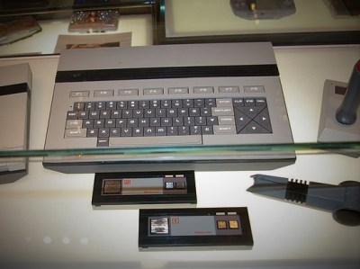
Video games were a dirty word in America in 1985. While games themselves were still happening on the microcomputer platforms, the home console business was virtually non-existent. Over in Japan, Nintendo was raking in money hand over fist selling video games on their Famicom console. They sought to replicate that success in North America by introducing a revised model of the Famicom, but it had to impress the tech journos that would be attending its reveal at the Consumer Electronics Show (CES).
The prototype system was called the Nintendo Advanced Video System (AVS). It would feature a keyboard, a cassette tape drive, and most importantly two wireless controllers. The controllers used infrared (IR) communication and the receiver was built-into the console deck itself. Each controller featured a square metallic directional pad and four action buttons that gave the impression of brushed aluminum. The advancement in video game controller technology was too good to be true though, because the entire system received a makeover before releasing as the Nintendo Entertainment System (NES) that Christmas. The NES lacked the keyboard, the tape drive, and the IR controllers and its change in materials hardly captured the high-end flash of the AVS. The removal of IR meant the device was cheaper to manufacture. A decision that ultimately helped the NES to become a breakout success that in turn brought back dedicated video game consoles single-handedly.
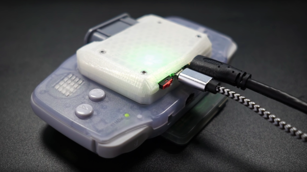
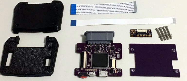
The concept of creating a gaming portable out of a home console has been around for some time, but it’s hardly seen the other way around. There have been a few devices that dared to straddle the line (i.e., Sega Nomad, Nintendo Switch, etc.), but the two worlds typically remain separate. [Stephen] looked to explore that space by attempting to turn the Game Boy Advance into a “big boy” console. The FPGA-based mod kit he created does just that, and comes complete with controller support and digital video output in 720p over a mini HDMI cable.
The kit itself was designed specifically for the original model GBAs containing the 40-pin LCD ribbon cable. These original models were the early run of non-backlit screens that are also denoted by a motherboard designation that can be seen by peering into the battery compartment. RGB signals are read directly from the GBA LCD socket by removing the handheld’s screen in favor of a fresh flat flex ribbon cable. This method enables a noise-free digital-to-digital solution as opposed to the digital-to-analog output of Nintendo’s own Game Boy Player add-on for the GameCube.
At an astonishing 240×160 native resolution, GBA video is scaled by the FPGA up to 5x within a 720p frame. Of course some of the image is cutoff in the process, so options for 4x and 4.5x scales were included. As a wise man once said, “Leave no pixel behind”. Since Nintendo designed the GBA clock to run at 59.7276 Hz, [Stephen] removed the oscillator crystal in order to sync the refresh rate to a more HDMI friendly 60 Hz. This means that the mod kit overclocks GBA games ever so slightly, though [Stephen] included a GBA cycle accurate mode as an option if your display can handle it.
The video below is [Stephen]’s initial test using a SNES controller. Tests must have gone well, because he decided to incorporate a SNES controller port in the final design. Now all those Super Nintendo ports on the GBA are back home once again thanks to this “consolizer” kit.
Here’s an interesting thought: it’s possible to build a cubesat for perhaps ten thousand dollars, and hitch a ride on a launch for free thanks to a NASA outreach program. Tracking that satellite along its entire orbit would require dozens or hundreds of ground stations, all equipped with antennas and a connection to the Internet. Getting your data down from a cubesat actually costs more than building a satellite.
This is the observation someone at Amazon must have made. They’ve developed the AWS Ground Station, a system designed to downlink data from cubesats and other satellites across an entire orbit. Right now, Amazon only has two ground stations attached, but they plan to have a dozen in place by the middle of next year. Each of these ground stations are associated with a particular AWS region (there are a total of sixteen AWS regions, which might limit the orbital coverage of the AWS Ground Station system), and consists of an antenna, an alt-az mount, and a gigantic bank of servers and hard drives to capture data from satellites orbiting overhead.
The Amazon blog post goes over how easy it is to capture data from a satellite, and it’s as easy as getting a NORAD ID, logging into your AWS account, and clicking a few buttons.
It should go without mention that this is the exact same idea behind SatNOGS, an Open Source global network of satellite ground stations and winner of the 2014 Hackaday Prize. One of their ground stations is what’s pictured at the top if this article. Right now, SatNOGS has over seventy ground stations in the network, including a few stations that are in very useful locations like the Canary Islands. The SatNOGS network already has a lot more coverage than the maximum of sixteen locations where Amazon has their data centers — made possible by its open nature. Congrats to the SatNOGS team once again for creating something so useful, and doing it four years before Amazon.
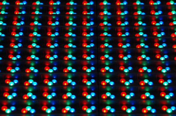
Building an LED matrix is a fun project, but it can be a bit of a pain. Usually it starts with hand-soldering individual LEDs and resistors together, then hooking them up to rows and columns so they can be driven by a microcontroller of some sort. That’s a lot of tedious work, but you can order an LED matrix pre-built to save some time and headache. You’ll still need a driver though, and while building one yourself can be rewarding there are many pitfalls and trade-offs to consider when undertaking that project as well. Or, you can consider one of a number of drivers that [deshipu] has outlined in detail.
The hangups surrounding the driver board generally revolve around the issue of getting constant brightness from LEDs regardless of how many in the row or column are illuminated at one time. Since they are typically driven one row or column at a time, the more that are on the lower the brightness each LED will have. Driver boards take different approaches to solving this problem, which usually involve a combination of high-speed scanning of the matrix or using a constant-current source in order to eliminate the need for resistors. [deshipu] outlines four popular chips that achieve these purposes, and he highlights their pros and cons to help anyone looking to build something like this.
Most of these boards will get you to an 8×8 LED matrix with no problem, with a few going a few pixels higher in either direction. That might be enough for most of our needs, but for something larger you’ll need other solutions like the one found in this 64×32 LED matrix clock. There are also even more complicated drivers if you go into extra dimensions.
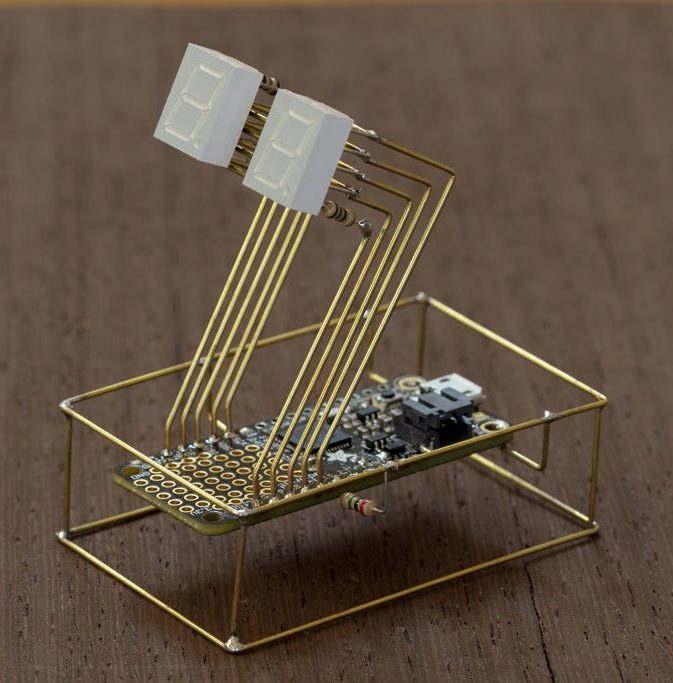
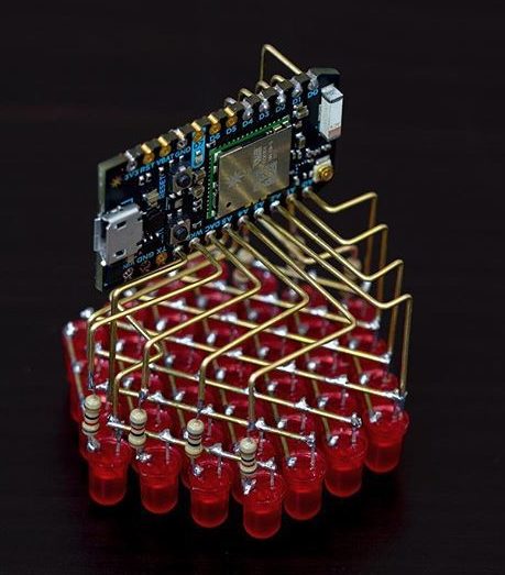
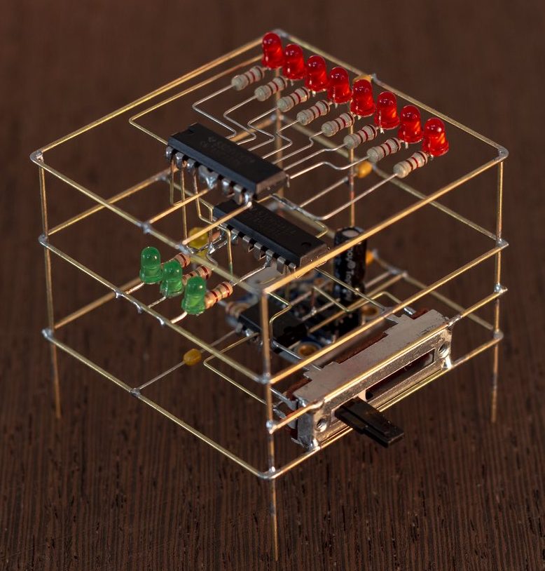
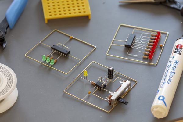
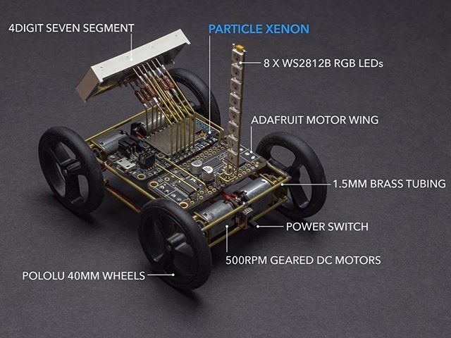
The technique of assembling circuits without substrate goes by many names; you may know it as flywiring, deadbugging, point to point wiring, or freeform circuits. Sometimes this technique is used for practical purposes like fixing design errors post-production or escaping tiny BGA components (ok, that one might be more cool than practical). Perhaps our favorite use is to create art, and [Mohit Bhoite] is an absolute genius of the form. He’s so prolific that it’s difficult to point to a particular one of his projects as an exemplar, though he has a dusty blog we might recommend digging through [Mohit]’s Twitter feed and marveling at the intricate works of LEDs and precision-bent brass he produces with impressive regularity.
So where to begin? Very recently [Mohit] put together a small wheeled vehicle for persistence of vision drawing (see photo above). We’re pretty excited to see some more photos and videos he takes as this adorable little guy gets some use! Going a little farther back in time there’s this microcontroller-free LED scroller cube which does a great job showing off his usual level of fit and finish (detail here). If you prefer more LEDs there’s also this hexagonal display he whipped up. Or another little creature with seven segment displays for eyes. Got those? That covers (most) of his last month of work. You may be starting to get a sense of the quality and quantity on offer here.
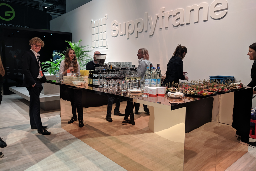
Hackaday’s parent company Supplyframe is at Electronica in Munich this week — booth C5-223. On Thursday from 16:00 – 18:00, they’ll be hosting a Hackaday Happy Hour, with a beer and coffee bar, for everyone in the Hackaday community. They’d love to see you and hear what you’re working on, be it for your day job or your night job.
If you missed the #badgelife exhibit at Supercon, it’s here at Electronica. There will also be some of those mysterious cubes you may have heard about. Richard Hogben and Bogdan Rosu will be DJing fresh beats. Stop by and say hi to [Sophi Kravitz], [Majenta Strongheart], [Alek Bradic], and everyone else from the Supplyframe team.
Hackaday’s own [Elliot Williams] will also be wandering around Electronica Wednesday afternoon. He can’t promise free beer, but if you want to crawl around Electronica with [Elliot], meet up at the Supplyframe booth at 14:30 on Wednesday.


 tiny BGA components (ok, that one might be more cool than practical). Perhaps our favorite use is to create art, and [Mohit Bhoite] is an absolute genius of the form. He’s so prolific that it’s difficult to point to a particular one of his projects as an exemplar, though he has