PLC Vs Arduino Show Down

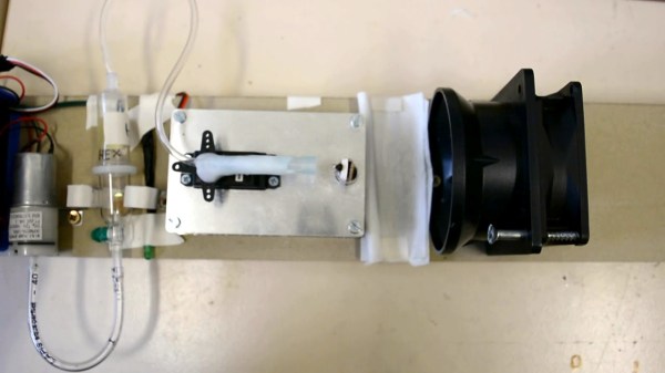
Hackaday readers don’t need an introduction to the Arduino. But in industrial control applications, programmable logic controllers or PLCs are far more common. These are small rugged devices that can do simple things like monitor switches and control actuators. Being ruggedized, they are typically reasonably expensive, especially compared to an Arduino. [Doug Reneker] decided to evaluate an Arduino versus a PLC in a relatively simple industrial-style application.

The application is a simple closed-loop control of flow generated by a pump. A sensor measures flow for the Arduino, which adjusts a control valve actuator to maintain the specified setpoint. The software uses proportional and integral control (the PI part of a PID loop).

Continue reading “PLC Vs Arduino Show Down”

Make Some Noise With The Typewriter Keyboard

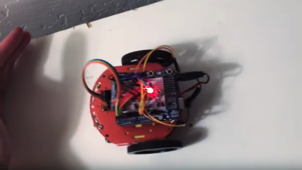
Are you an angry programmer? Do you get the frequent urge to smash the return key or space bar after finishing every single line of code? Well then [Konstantin Schauwecker]’s typewriter keyboard is just the thing for you. In his project, [Konstantin] hacked a German Olympia Monica typewriter into a USB keyboard.

The project uses no less than 50 photo interrupters mounted on a custom PCB that mounts directly under the typewriter itself. The circuit board is so designed that the hammer arms take a position in obstructing the opto-interrupters. Every time a key is pressed, the corresponding device sends a signal to an Arduino.

In order to enable the wiring of 50 signals to an Arduino Leonardo, multiplexers and decoders are employed. CD4515, 4×16 line decoders work to activate the optical signals and the CD4067, 16×4 multiplexers are used to return the scans. This forms the traditional scanning keyboard matrix and the whole thing is managed in the Arduino code (available as a zip file).

This project can be a great starting point for anyone who wants to hack their grandpa’s old typewriter or make one in order to annoy the guy sitting next to them. Check out the video below for a demo and teardown and if you prefer Raspberry Pis then check out this mechanical typewriter hack.

Reflective Sensor Becomes Kart Racing Lap Counter

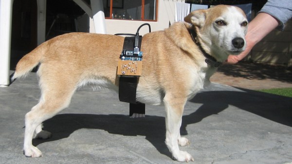
Once you have a track and a kart to race on it, what’s missing? A lap counter that can give your lap times in hardcopy, obviously! That’s what led [the_anykey] to create the Arduino-based Lap Timer to help him and his kids trim those precious seconds off their runs, complete with thermal printer for the results.

The hardware uses an infrared break-beam sensor module (a Velleman PEM10D) to detect when a kart passes by. This module is similar to a scaled-up IR reflective object sensor; it combines an IR emitter and receiver on one end, and is pointed at a reflector placed across the track, up to 10 meters away. When a kart breaks the beam, the module reports the event to the rest of the hardware. Only needing electronics on one side allows the unit to be self-contained.

An obvious shortcoming of this system is the inability to differentiate between multiple karts, but for timing a single driver’s performance it does the trick. What’s great about this project is it showcases how accessible hardware is today; a device like this is possible to put together with what are essentially off-the-shelf components available to any hobbyist, using an Arduino as the glue to hold it together. We’d only comment that a red-tinted piece of plastic as an overlay for the red display (and a grey-tinted one for the green) would make the LED displays much easier to read. Still, this is a very clean and well-documented build. See it in action in the video embedded below.

Continue reading “Reflective Sensor Becomes Kart Racing Lap Counter”

JPEG Decoding, Arduino Style

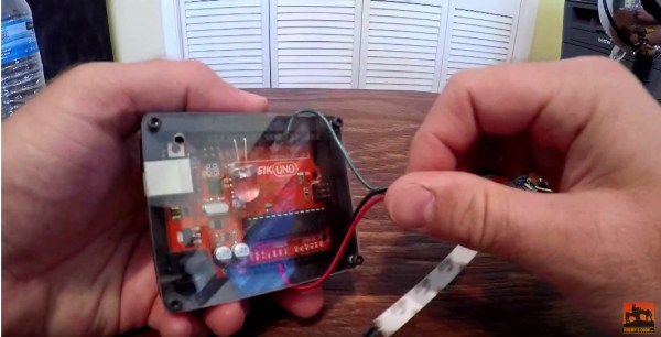
When you think of image processing, you probably don’t think of the Arduino. [Jan Gromes] did, though. Using a camera and an Arduino Mega, [Jan] was able to decode input from an Arduino-connected camera into raw image data. We aren’t sure about [Jan’s] use case, but we can think of lots of reasons you might want to know what is hiding inside a compressed JPEG from the camera.

The Mega is key, because–as you might expect–you need plenty of memory to deal with photos. There is also an SD card for auxiliary storage. The camera code is straightforward and saves the image to the SD card. The interesting part is the decoding.

Continue reading “JPEG Decoding, Arduino Style”

Tinkercad Does Arduino

If you’ve done 3D printing, you’ve probably at least heard of Tinkercad. This popular CAD package runs in your browser and was rescued from oblivion by Autodesk a few years ago. [Chuck] recently did a video about a new Tinkercad feature: building and simulating virtual Arduino circuits. You can watch it below.

There are a variety of components you can add to your design. You’ll find an integrated code editor and a debugger. You can even get to the serial monitor, all in your browser with no actual Arduino hardware. You can also build simple circuits that don’t use an Arduino, although the component selection is somewhat limited.

Continue reading “Tinkercad Does Arduino”

Robot Solves Sudoku On Paper

Sudoku is a great way to pass some time, especially on a long flight. However, we don’t think the airlines will let [Sanahm] board with his sudoku-solving robot. The basic machine looks like a 2D plotter made with aluminum extrusion, with the addition of a Raspberry Pi and a camera. The machine can read a sudoku puzzle, solve it, and then fill in the puzzle with a pen. Unlike humans, it should never need to erase its work.

The software uses OpenCV to process the camera data, find the grid, and the cells provided by the puzzle. TensorFlow recognizes the numbers. From there, it is all just math to solve the puzzle. Once solved, the plotter part of the robot takes over and fills in the blanks. After all that, this seems like the easy part.

Continue reading “Robot Solves Sudoku On Paper”

A Live ECU Simulator For OBD2 Projects

If you are working with OBD2 hardware or software, it’s easy enough to access test data, simply plug into a motor vehicle with an OBD2 socket. If, however, you wish to test OBD2 software under all possible fault conditions likely to be experienced by an engine, you are faced with a problem in that it becomes difficult to simulate all faults on a running engine without breaking it. This led [Fixkick] to create an OBD2 simulator using a secondhand Ford ECU supplied with fake sensor data from an Arduino to persuade it that a real engine was connected.

The write-up is quite a dense block of text to wade through, but if you are new to the world of ECU hacking it offers up some interesting nuggets of information. In it there is described how the crankshaft and camshaft sensors were simulated, as well as the mass airflow sensor, throttle position, and speedometer sensors. Some ECU inputs require a zero-crossing signal, something achieved with the use of small isolating transformers. The result is a boxed up unit containing ECU and Arduino, with potentiometers on its front panel to vary the respective sensor inputs.

We’ve brought you quite a few OBD2 projects over the years, for example, there was this LED tachometer, and a way into GM’s OnStar.

Thanks [darkspr1te] for the tip.