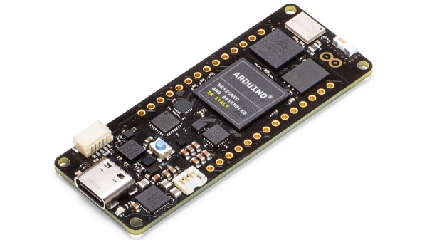
It’s amazing to see how much technology is packed into even the “simple” devices that we take for granted in modern life. Case in point, the third party Xbox controller that [wrongbaud] recently decided to tear into. Not knowing what to expect when he cracked open its crimson red case, inside he found an ARM Cortex microcontroller and a perfect excuse to play around with Serial Wire Debug (SWD).
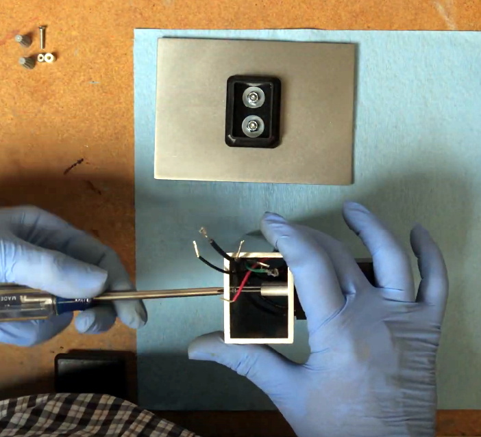
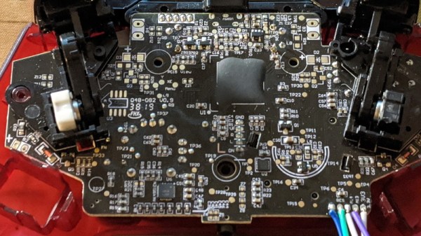
Though even figuring out that much took a bit of work. As is depressingly common, all the interesting components on the controller’s PCB were locked away behind a black epoxy blob. He had no idea what chip was powering the controller, much less that debugging protocols it might support. But after poking around the board with his multimeter, he eventually found a few test points sitting at 3.3 V which he thought was likely some kind of a programming header. After observing that pulling the line labelled “RES” low reset the controller, he was fairly sure he’d stumbled upon a functional JTAG or SWD connection.
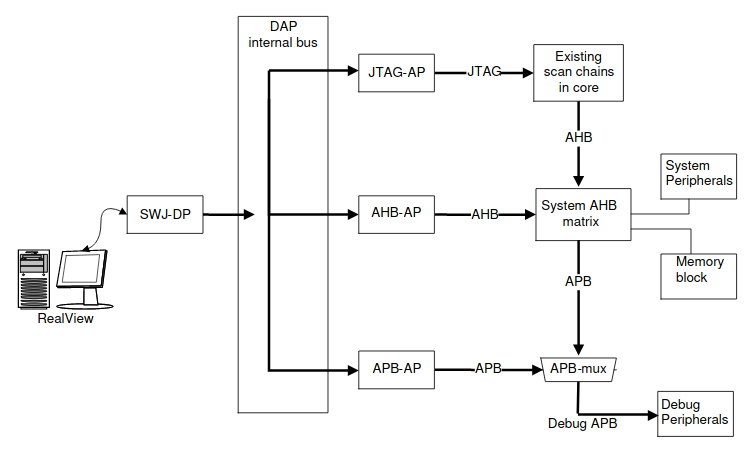
As [wrongbaud] explains in his detailed blog post, SWD is something of a JTAG successor that’s commonly used by ARM hardware. Using just two wires (data and clock), SWD provides hardware debugging capabilities on pin constrained platforms. It allows you to step through instructions, read and write to memory, even dump the firmware and flash something new.
For the rest of the post, [wrongbaud] walks the reader through working with an SWD target. From compiling the latest version of OpenOCD and wiring an FTDI adapter to the port, all the way to navigating through the firmware and unlocking the chip so you can upload your own code.
To prove he’s completely conquered the microcontroller, he ends the post by modifying the USB descriptor strings in the firmware to change what it says when the controller is plugged into the computer. From here, it won’t take much more to get some controller macros like rapid fire implemented; a topic we imagine he’ll be covering in the future.
This post follows something of a familiar formula for [wrongbaud]. As part of his continuing adventures in hardware hacking, he finds relatively cheap consumer devices and demonstrates how they can be used as practical testbeds for reverse engineering. You might not be interested in changing the ROM that a Mortal Kombat miniature arcade cabinet plays, but learning about the tools and techniques used to do it is going to be valuable for anyone who wants to bend silicon to their will.


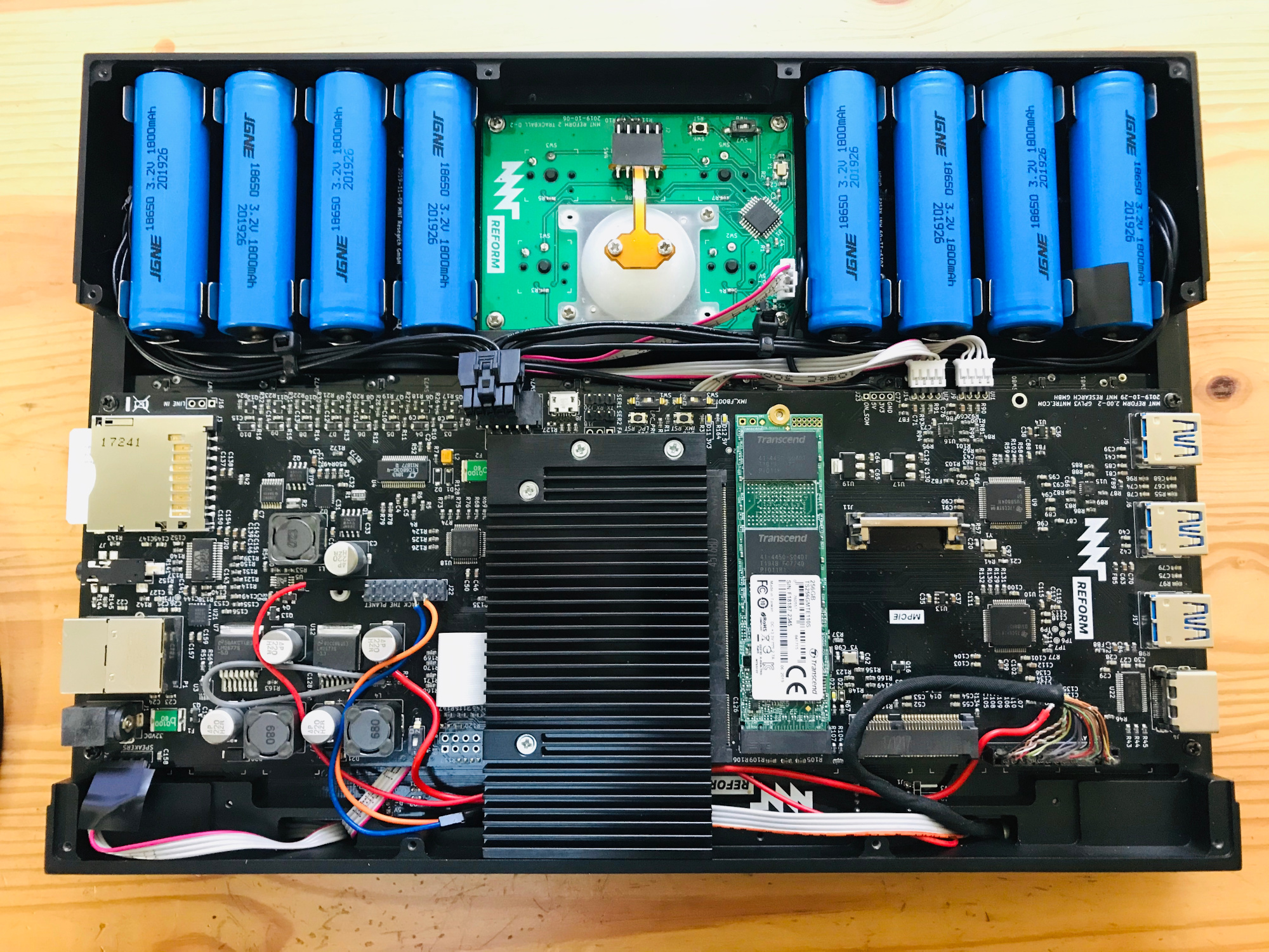 Since we started eagerly watching the Reform