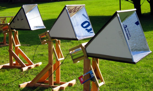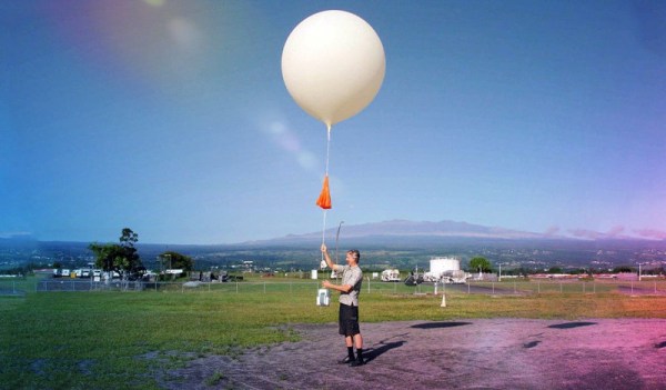
Meteorological organisations across the world launch weather balloons on a regular basis as a part of their work in predicting whether or not it will rain on the weekend. Their payloads are called radiosondes, and these balloons deliver both telemetry and location data throughout their flightpath. Hobbyists around the globe have devoted time and effort to tracking and decoding these signals, and now it’s possible to do it all automatically, thanks to Radiosonde Auto RX.
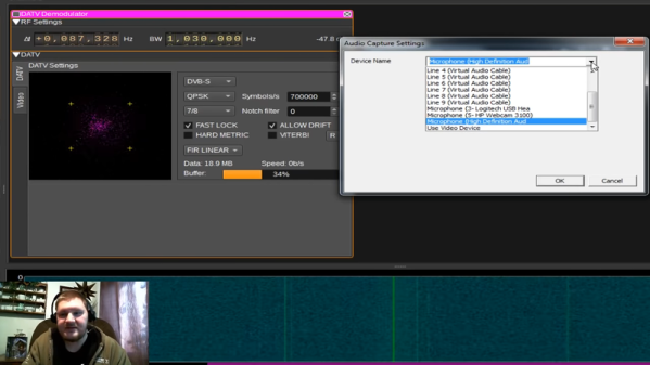
The basis of the project is the RTL-SDR, everyone’s favourite low-cost software defined radio receiver. In this case, software is used to first hunt for potential radiosonde signals, before then decoding them and uploading the results to a variety of online services. Some of these are designed for simple tracking, while others are designed for live chase and recovery operations. Currently, the software only covers 3 varieties of radiosonde, but the team are eager to expand the project and have requested donations of other radiosondes for research purposes.
The team recently conducted a talk at linux.conf.au regarding the project, which goes into detail as to the decoding and tracking of the radiosonde data. If you’re eager to try it out, download the software, fetch your TV dongle and get cracking. You might also consider tracking cubesats while you’re at it. Video after the break.
via [crazyoperator], thanks to Slds Ernesto for the tip!
Continue reading “Automated Radiosonde Tracking Via Open Source”