Conceptually speaking, a liquid propellant rocket engine is actually a very simple piece of hardware. All you need to do is spray your fuel and oxidizer into the combustion chamber at the proper ratio, add a spark, and with a carefully designed nozzle you’re off to the races. Or the Moon, as the case may be. It’s just that doing it in the real-world and keeping the whole thing from exploding for long enough to do some useful work is another story entirely.
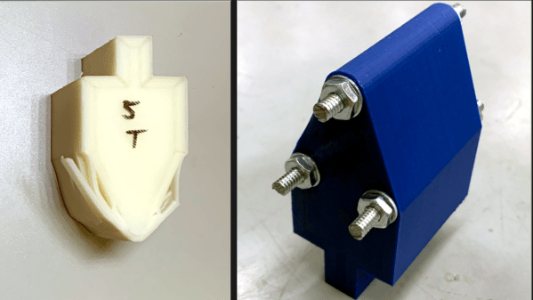
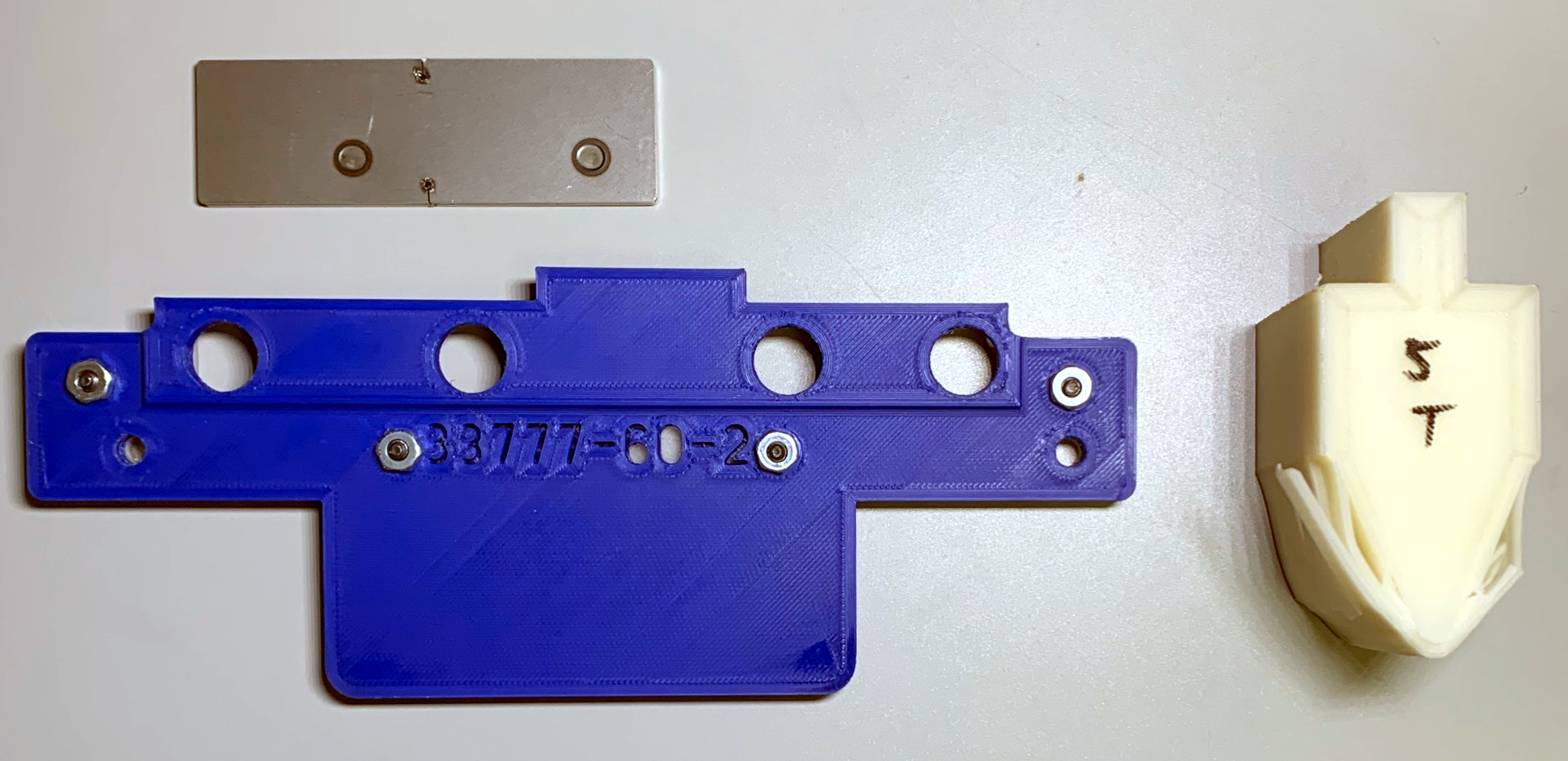
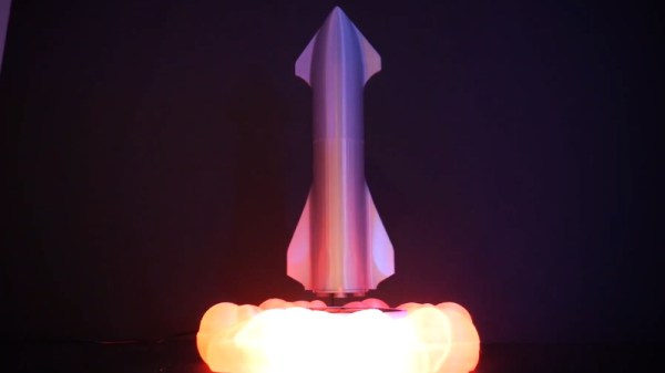
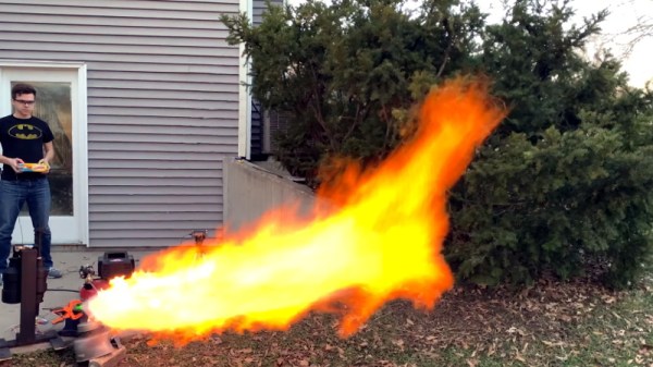
Taking the process one step at a time, [Luke Walters] has been working on a 3D printed injector that tackles the first half of the problem. After nearly a dozen different prototypes, he’s come up with a printable injector design that atomizes the fuel and combines it with pressurized air at a suitable ratio for combustion. As you can see in the video at the break, it’s certainly capable of generating some impressive fireballs.
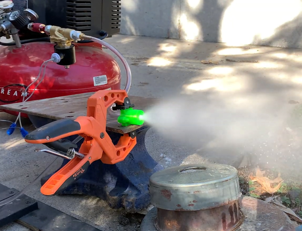
The internal passages of the injector have been designed in such a way that fuel (91% isopropyl alcohol) and air are spinning in opposite directions when they meet. This promotes more complete mixing, which in turn leads to a more efficient burn. Originally developed in the 1930s, so-called “swirl injectors” of this type were one of the key technological advancements made by Germany’s V-2 rocket program. Some ideas never go out of style.
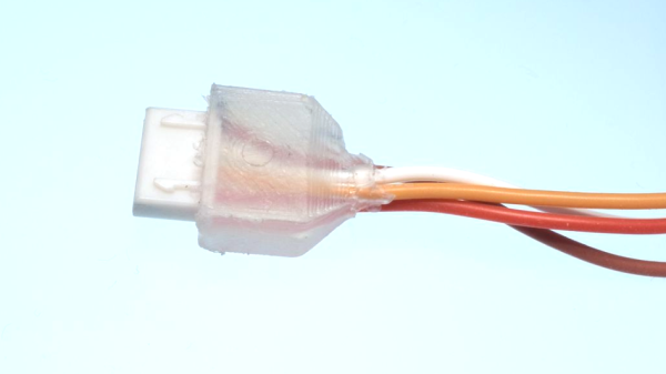
Since the injector only touches the fuel and air prior to ignition, it doesn’t need to be particularly heat resistant. To be on the safe side [Luke] has printed the part in PETG at 100% infill, but in reality the flame front is far enough away that temperature isn’t much of a concern. That said, he does hope to eventually fit these injectors into some kind of combustion chamber, which is where things will start getting toasty.
To be clear this is not a rocket engine, and it produces no appreciable thrust. Turning a big flame into a useful means of propulsion is where things get tricky, almost as though it’s rocket science or something. But that doesn’t mean it can’t be done by suitably ambitious hackers.
Continue reading “3D Printed Swirl Rocket Injector Turns Up The Heat”