Most of us have beheld the sonic glory of an Atari Punk Console, that lo-fi synth whose classic incarnation is a pair of 555 timers set up to warble and bleep in interesting ways. Very few of us, however, have likely seen an APC built from 555s that are made from vacuum tubes.
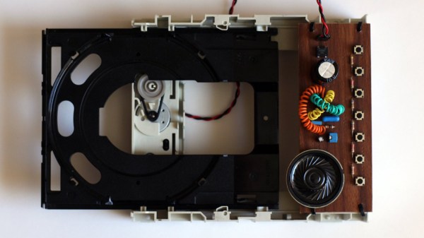
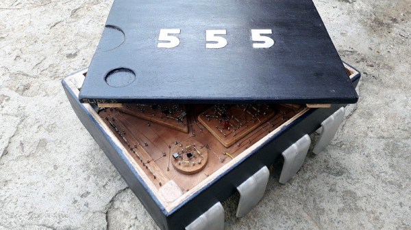
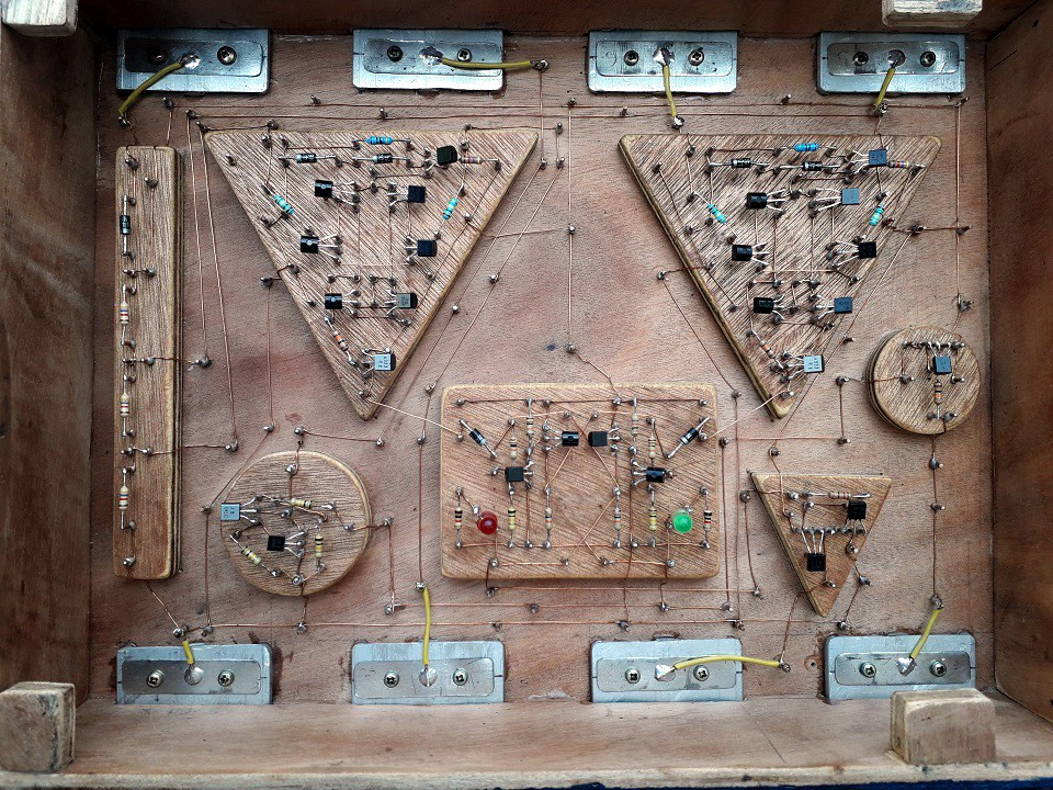
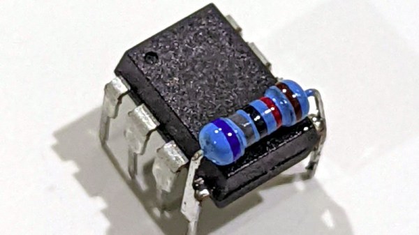
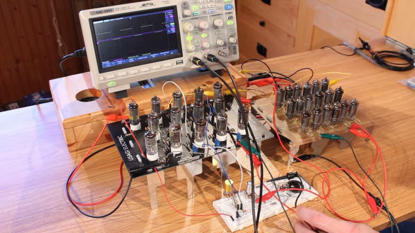
It’s little surprise to regular readers that this one comes to us by way of [David] at Usagi Electric, who hasn’t met a circuit that couldn’t be improved by realizing it in vacuum tubes. His “hollow-state” Atari Punk Console began with the 18-tube version of the 555 that he built just for fun a while back, which proved popular enough that he’s working on a kit version, the prototype of which served as the second timer for the synth. With 32 tubes aglow amid a rats-nest of jumpers, the console managed to make the requisites sounds, but lacked a certain elegance. [David] then vastly simplified the design, reducing the BOM to just four dual-triode tubes. Housed on a CNC milled PCB in a custom wood box, the synth does a respectable job and looks good doing it. The video below shows both versions in action, as well as detailing their construction.
As cool as a vacuum tube synth may be, we realize that not everyone goes for the hot glass approach. No worries — plenty of silicon Atari Punk Consoles to choose from here. There’s one built into a joystick, a circuit sculpture version complete with mini-CRT, or even eight APCs teamed up with MIDI control.
Continue reading “The Atari Punk Console, Now With More Vacuum Tubes”