Small low-cost CNC mill with rotary tool

Minimal Mill: The Minamil

Having a few machine tools at one’s disposal is a luxury that not many of us are afforded, and often an expensive one at that. It is something that a large percentage of us may dream about, though, and with some commonly available tools and inexpensive electronics a few people have put together some very inexpensive CNC machines. The latest is the Minamil, which uses a rotary tool and straps it to an economical frame in order to get a functional CNC mill setup working.

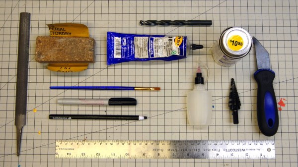
This project boasts impressively low costs at around $15 per axis. Each axis uses readily available parts such as bearings and threaded rods that are readily installed in the mill, and for a cutting head the build is based on a Dremel-like rotary tool that has a similarly low price tag. Let’s not ignore the essentially free counterweight that is used.

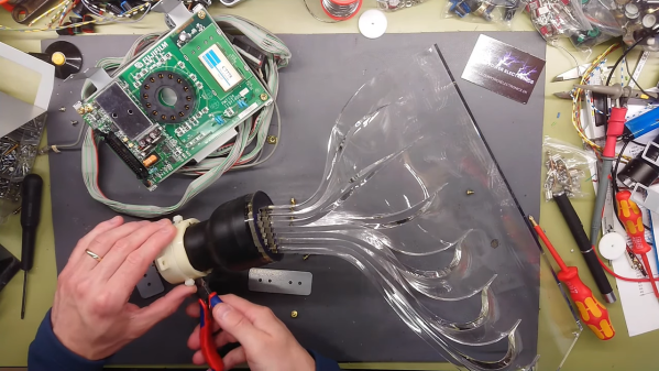
For control, an Arduino with a CNC shield powers the three-axis device which is likely the bulk of the cost of this project. [Paul McClay] also points out that a lot of the material he needed for this build can be salvaged from things like old printers, so the $45 price tag is a ceiling, not a floor.

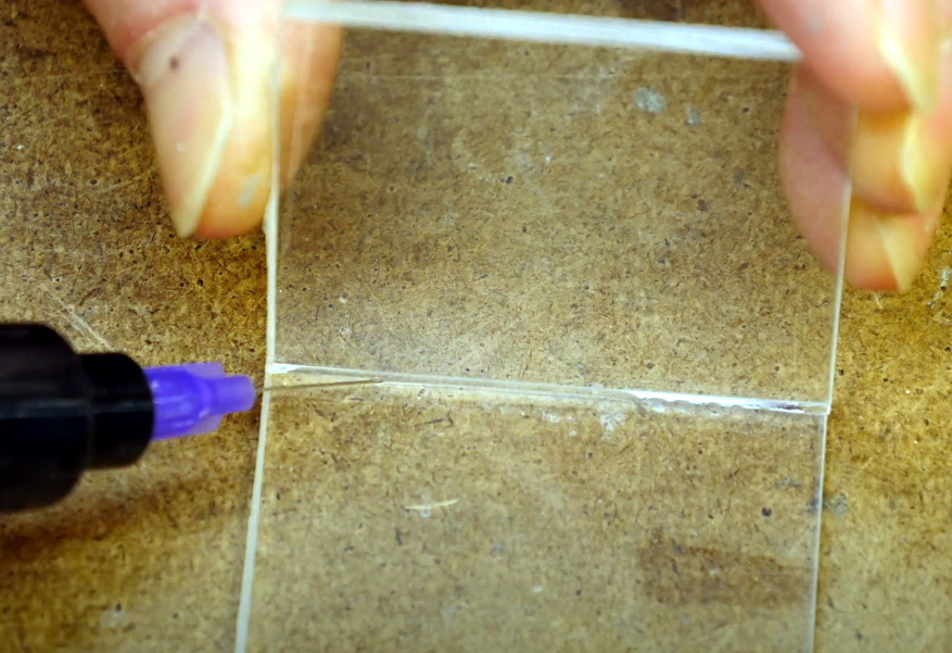
The Minamil has been demonstrated milling a wide variety of materials with excellent precision. Both acrylic and aluminum are able to be worked with this machine, but [Paul] also demonstrates it in its capacity to mill PCBs. It does have some limitations but for the price it seems that this mill can’t be beat, even compared to his previous CNC build which repurposed old CD drives.

Math, Optics, And CNC Combine To Hide Secret Images In Acrylic

Magic mirrors, with an LCD panel hidden behind a partially reflectively mirror, are popular for a reason — they’re a good-looking way to display useful information. A “Magic Window,” however, is an entirely different thing — and from the look of it, a far cooler one.

If you’ve never seen a Magic Window before, don’t worry — it’s partially because you’re not supposed to see it. A Magic Window appears to be a clear piece of glass or plastic, one with a bit of a wave in it that causes some distortion when looking through it. But as [Matt Ferraro] explains, the distortion encodes a hidden image, visible only when light passes through the window. It looks a bit like a lithophane, but it’s projected rather than reflected, and it relies on an optical phenomenon known as caustics. If you’ve ever seen the bright and dark patches cast on the bottom of a swimming pool when sunlight hits the surface, you’ve seen caustics.

As for how to hide an image in a clear window, let’s just say it takes some doing. And some math; Snell’s Law, Fermat’s Theorem, Poisson’s Equation — all these and more are mentioned by [Matt] by way of explanation. The short story is that an image is morphed in software, normalized, and converted into a heightmap that’s used to generate a toolpath for a CNC router. The design is carved into a sheet of acrylic by the router and polished back to clarity with a succession of sandpaper grits. The wavy window is then ready to cast its hidden shadow.

Honestly, the results are amazing, and we marvel at the skills needed to pull this off. Or more correctly, that [Matt] was able to make the process simple enough for anyone to try.

Continue reading “Math, Optics, And CNC Combine To Hide Secret Images In Acrylic”

How To Build With Acrylic Using The Tools You Have

In a perfect world, we’d all have laser cutters and could pop intricate designs out of acrylic sheets with just a few clicks of the mouse. But in reality, most of us have to make do with the pedestrian tools we have at hand. For many, that might even mean everything has to be done by hand. Luckily, [Eric Strebel] has been working on a series of videos that cover how you can make professional looking parts out of acrylic using a wide array of common tools.

Solvent welding hand-cut pieces of acrylic.

The first video demonstrates how a simple cube can be constructed by a band saw, a table saw, and if need be, with hand tools. You might think the two power saws would have similar results, but as [Eric] explains, the table saw ends up being far more accurate and requires less post-processing to get a smooth edge. Ideally you’d run the cut pieces through a router to bevel them, but that’s a tall order for many home gamers.

As for the hand tool approach, scoring and snapping the sheets ends up making a surprisingly clean break that can actually be cleaner than the edge you’d get with a power tool. No matter how you cut them, [Eric] shows the proper way to apply the water-like solvent to your acrylic pieces to create a strong and visually attractive bond.

The next video in the series covers more advanced techniques that can still be pulled off without a top-of-the-line workshop. Sure the water-cooled acrylic bender he has is pretty slick, but if you can’t afford the $100 USD gadget, he shows you how to get similar results with an old toaster oven that you can pick up from the thrift store or even the side of the road. With some hand-made jigs and molds, you can warp and flex the heated plastic into whatever shape your project needs. Combining the tips from both videos, you might be surprised at what can be created with little more than a ruler, some hot air, and the appropriate techniques.

These are just the latest in a long line of fantastic videos that [Eric Strebel] has produced about at-home design and fabrication. Whether its making a two part silicone mold or creating functional prototypes out of foam board, there’s an excellent chance that he’s covered a topic you’ve wanted to learn more about.

Continue reading “How To Build With Acrylic Using The Tools You Have”

Flexible Prototyping For E-Textiles That Doesn’t Cost An Arm And A Leg

Let’s face it: pretty much everything about e-textiles is fiddly. If wearables were easy, more people would probably work in that space. But whereas most circuit prototyping is done in two dimensions, the prototyping of wearables requires thinking and planning in 3D. On top of that, you have to figure out how much conductive thread you need, and that stuff’s not cheap.

[alch_emist] has a method for arranging circuits in 3D space that addresses the harsh realities of trying to prototype wearables. There’s that whole gravity thing to deal with, and then of course there are no straight lines anywhere on the human body. So here’s how it works: [alch_emist] made a bunch of reusable tie points designed to work with an adhesive substrate such as felt. They laser-cut a set of acrylic squares and drilled a hole in each one to accommodate a neodymium magnet. On the back of each square is a small piece of the hook side of hook-and-loop tape, which makes the tie points stay put on the felt, but rearrange easily.

We love the idea of prototyping with felt because it’s such a cheap and versatile fabric, and because you can easily wrap it around your arm or leg and see how the circuit will move when you do.

Not quite to this planning stage of your next wearable project? Magnets and conductive thread play just as well together in 2D.

Digital X-Ray Scanner Teardown Yields Bounty Of Engineering Goodies

We’ll just go ahead and say it right up front: we love teardowns. Ripping into old gear and seeing how engineers solved problems — or didn’t — is endlessly fascinating, even for everyday devices like printers and radios. But where teardowns really get interesting is when the target is something so odd and so specialized that you wouldn’t normally expect to get a peek at the outside, let alone tramp through its guts.

[Mads Barnkob] happened upon one such item, a Fujifilm FCR XG-1 digital radiography scanner. The once expensive and still very heavy piece of medical equipment was sort of a “digital film system” that a practitioner could use to replace the old-fashioned silver-based films used in radiography, without going all-in on a completely new digital X-ray suite. It’s a complex piece of equipment, the engineering of which yields a lot of extremely interesting details.

The video below is the third part of [Mads]’ series, where he zeroes in on the object of his desire: the machine’s photomultiplier tube. The stuff that surrounds the tube, though, is the real star, at least to us; that bent acrylic light pipe alone is worth the price of admission. Previous videos focused on the laser scanner unit inside the machine, as well as the mechatronics needed to transport the imaging plates and scan them. The video below also shows experiments with the PM tube, which when coupled with a block of scintillating plastic worked as a great radiation detector.

We’ve covered a bit about the making of X-rays before, and a few of the sensors used to detect them too. We’ve also featured a few interesting X-ray looks inside of tech, from a Starlink dish to knock-off adapters.

Continue reading “Digital X-Ray Scanner Teardown Yields Bounty Of Engineering Goodies”

Transparent Hard Drive Gives Peek At The Platters

Solid-state drives (SSDs) are all the rage these days, and for good reason. But that doesn’t mean the era of the spinning disk is over, as traditional mechanical hard drives still offer a compelling value for mass storage applications where access times aren’t as critical. But the components inside these “slow” mechanical drives are still moving at incredible speeds, which [The Developer Guy] has nicely illustrated with his transparent hard drive.

Now unfortunately the technology to produce a fully transparent hard drive doesn’t exist, but laser cutting a new top plate out of acrylic is certainly within the means of the average hacker. The process is pretty straightforward: cut out a piece of clear plastic in the same shape and size as the drive’s original lid, put the appropriate mounting holes in it, and find some longer screws to accommodate the increased thickness.

Because this is just for a demonstration, [The Developer Guy] doesn’t need to worry too much about dust or debris getting on the platters; but we should note that performing this kind of modification on a drive you intend on actually using would be a bad idea unless you’ve got a cleanroom to work in.

In the videos below [The Developer Guy] records the drive while it’s in use, and at one point puts a microscope on top of the plastic to get a close-up view of the read/write head twitching back and forth. We particularly liked the time-lapse of the drive being formatted, as you can see the arm smoothly moving towards the center of the drive. Unfortunately the movement of the platters themselves is very difficult to perceive given their remarkably uniform surface, but make no mistake, they’re spinning at several thousand RPM.

Have an old mechanical drive of your own that you’re not sure what to do with? We’ve seen them turned into POV clocks, impromptu rotary encoders, and even surprisingly powerful blower fans.

Continue reading “Transparent Hard Drive Gives Peek At The Platters”

Clock-of-Clocks Adds Light-Pipe Hands For Beauty And Function

We’ve gotten used to seeing “meta clocks,” clocks that use an array of analog clock faces and piece together characters using the hands of the clocks. They’re very clever, and we always like to see them, especially when they come with detailed build instructions like this one does.

What’s also nice about [Erich Styger]’s “MetaClockClock” display is the twist on the original concept. Where most clock-of-clocks depend on the contrast between the hands and the faces of the analog movements, [Erich] added light to the mix. Hidden inside the bezel of each clock is a strip of RGB LEDs; coupled with the clear acrylic hands of the clock, which act as light pipes, each clock can contribute different shapes of different colors to the display. Each clock is built around a dual-shaft stepper motor of the kind used in car dashboard gauges; the motors each live on a custom PCB, while the LEDs are mounted on a ring-shaped PCB of their own. Twenty-four of the clocks are mounted in a very nice walnut panel, which works really well with the light-pipe hands. The video below shows just some of the display possibilities.

[Erich] has documented his build process in extreme detail, and has all the design files up on GitHub. We won’t say that recreating his build will be easy — there are a lot of skills needed here, from electronics to woodworking — but at least all the information is there. We think this is a beautiful upgrade to [Erich]’s earlier version, and we’d love to see more of these built.

Continue reading “Clock-of-Clocks Adds Light-Pipe Hands For Beauty And Function”