3D Printed WiFi Reflectors Custom Designed For The Building

Are you a wizard at antenna design? Chances are you’ve never even given it a try, but this tool could change that. Most home-made WiFi signal boosting antenna plans around the Internet share one feature: they are directional antennas or reflectors. But WiPrint is a tool for designing custom WiFi reflectors that map to the specific application.

If we want to increase the signal strength in two or three different locations the traditional solution is an omnidirectional antenna. The problem is, although a good omnidirectional antenna increases the signal power in those locations we want, it also increases the signal power where we don’t want.

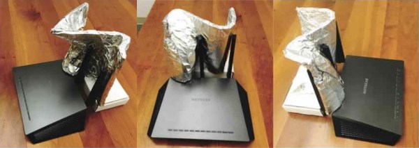
A team of researchers led by Dartmouth College created WiPrint to allow users to input a floor plan, the location of the WiFi access point and a desired signal map into the system. The software uses an optimization algorithm to produce a custom reflector shape for that floor plan. The reflector can then be fabricated and placed next to the access point antenna to reflect and concentrate the signal in the specified area, while decreasing signal strength outside of it. The best thing is: you can actually 3D print the reflector and just glue tin foil on it!

The results show that optimized reflectors can weaken or enhance signals in target areas by up to 10 or 6 dB, respectively, and resulting in throughput changes by up to -63.3% or 55.1%. That is not the only advantage, as the researchers point out:

Our approach provides four benefits. First, it provides strong physical security by limiting the physical reach of wireless signals, hence creating a virtual wall for wireless signals. Second, it relies on a low-cost ($35), reproducible 3D reflector, which can be easily replaced upon substantial changes in the environment or coverage requirement. Third, it offers an easily accessible and easy-to-configure solution to non-expert users. Users only need to specify coverage requirements and a coarse environment model, with which our system computes a reflector shape tailored to the built environment. Finally, it is applicable to commodity low-end Wi-Fi APs without directional or multiple antennas.

The sad part is that, for now, no software is available. The study and results have just been presented at ACM’s BuildSys 2017. It would be great to see something like this open-sourced. Meanwhile, this is further proof that [Brian Benchoff] knew what he was doing when he told you to use duct tape for superior WiFi range.

[Jeri] Builds A Magnetic Loop Antenna

Most new hams quickly learn that the high-frequency bands are where the action is, and getting on the air somewhere between 40- and 160-meters is the way to make those coveted globe-hopping contacts. Trouble is, the easiest antennas to build — horizontal center-fed dipoles — start to claim a lot of real estate at these wavelengths.

So hacker of note and dedicated amateur radio operator [Jeri Ellsworth (AI6TK)] has started a video series devoted to building a magnetic loop antenna for the 160- and 80-meter bands. The first video, included after the break, is an overview of the rationale behind a magnetic loop. It’s not just the length of the dipole that makes them difficult to deploy for these bands; as [Jeri] explains, propagation has a lot to do with dipole height too. [Jeri] covers most of the mechanical aspects of the antenna in the first installment; consuming a 50-foot coil of 3/4″ copper tubing means it won’t be a cheap build, but we’re really looking forward to seeing how it turns out.

We were sorry to hear that castAR, the augmented reality company that [Jeri] co-founded, shut its doors back in June. But if that means we get more great projects like this and guided tours of cool museums to boot, maybe [Jeri]’s loss is our gain?

Continue reading “[Jeri] Builds A Magnetic Loop Antenna”

Snazzy Balun Lets Ham Use Off-The-Shelf Coax

It’s a dilemma many hams face: it’s easy to find yourself with a big spool of RG-11 coax cable, usually after a big cable TV wiring project. It can be tempting to use it in antenna projects, but the characteristic impedance of RG-11 is 75 Ω, whereas the ham world is geared to 50 Ω. Not willing to waste a bounty of free coax, one ham built a custom 1:1 current balun for a 75 Ω dipole.

Converting between balanced and unbalanced signals is the job of a balun, and it’s where the device derives its name. For hams, baluns are particularly useful to connect a dipole antenna, which is naturally balanced, to an unbalanced coax feedline. The balun [NV2K] built is a bifilar 1:1 design, with two parallel wires wound onto a ferrite core. To tweak the characteristic impedance to the 75 Ω needed for his antenna and feedline, [NV2K] added short lengths of Teflon insulation to one of the conductors, which is as fussy a bit of work as we’ve seen in a while. We appreciate the careful winding of the choke and the care taken to make this both mechanically and electrically sound, and not letting that RG-11 go to waste is a plus.

With as much effort as hams put into antenna design, there’s a surprising dearth of Hackaday articles on the subject. We’ve talked a bit about the Yagi-Uda antenna, and we’ve showcased a cool magnetic loop antenna, but there’s precious little about the humble dipole.

[via r/amateurradio]

FM Snake Feeds Off Radio Waves

[Eric Brasseur] built a radio-detecting snake that consists of a LED that lights up when around reasonably strong radio waves. Near an FM radio mast you’ll find a huge amount of waste energy being dumped out in the 88 to 108 MHz range.

[Eric]’s rig consists of a pair of 1N6263 Schottky diodes, flip-flopped with one set of ends soldered to the antenna and the other ends soldered to the leads of the LED with about a foot of wire in between. The antenna can be a single wire as the diodes are soldered together. This one is around 4 feet in length for a total length of around 160 cm or a little over 5 feet. He went with a red LED just to give it a greater chance of being seen when illuminated by a distant or weak source of radio waves.

Hackaday loves its radio hacks; check out our posts on improving WiFi throughput with FM radio and building a modern DIY FM radio.

[Thanks, Alain!]

Piezomagnetic Trick Shrinks 2.5 GHz Antennas

To a ham radio operator used to “short”-wave antennas with lengths listed in tens of meters, the tiny antennas used in the gigahertz bands barely even register. But if your goal is making radio electronics that’s small enough to swallow, an antenna of a few centimeters is too big. Physics determines plausible antenna sizes, and there’s no way around that, but a large group of researchers and engineers have found a way of side-stepping the problem: resonating a nano-antenna acoustically instead of electromagnetically.

Normal antennas are tuned to some extent to the frequency that you want to pick up. Since the wavelength of a 2.5 GHz electromagnetic wave in free space is 120 cm mm, most practical antennas need a wire in the 12-60 cm mm range to bounce signals back and forth. The trick in the paper is to use a special piezomagnetic material as the antenna. Incoming radio waves get quickly turned into acoustic waves — physical movement in the nano-crystals. Since these sound waves travel a lot slower than the speed of light, they resonate off the walls of the crystal over a much shorter distance. A piezoelectric film layer turns these vibrations back into electrical signals.

Ceramic chip antennas use a similar trick. There, electromagnetic waves are slowed down inside the high-permittivity ceramic. But chip antennas are just slowing down EM waves, whereas the research demonstrated here is converting the EM to sound waves, which travel many orders of magnitude slower. Nice trick.

Granted, significant material science derring-do makes this possible, and you’re not going to be fabricating your own nanoscale piezomagnetic antennas any time soon, but with everything but the antenna getting nano-ified, it’s exciting to think of a future where the antennas can be baked directly into the IC.

Thanks [Ostracus] for the tip in the comments of this post on antenna basics. Via [Science Magazine].

Antenna Basics By Whiteboard

Like a lot of people, [Bruce] likes radio controlled (RC) vehicles. In fact, many people get started in electronics motivated by their interest in RC. Maybe that’s why [Bruce] did a video about antenna basics where he spends a little more than a half hour discussing antennas. You can see the video below.

[Bruce] avoids any complex math and focuses more on intuition about antennas, which we like. Why does it matter that antennas are cut to a certain length? [Bruce] explains it using a swing and a grandfather clock as an analogy. Why do some antennas have gain? Why is polarization important? [Bruce] covers all of this and more. There’s even a simple experiment you can do with a meter and a magnet that he demonstrates.

Continue reading “Antenna Basics By Whiteboard”

Doppler Module Teardown Reveals The Weird World Of Microwave Electronics

Oscillators with components that aren’t electrically connected to anything? PCB traces that function as passive components based solely on their shape? Slots and holes in the board with specific functions? Welcome to the weird and wonderful world of microwave electronics, brought to you through this teardown and analysis of a Doppler microwave transceiver module.

We’ve always been fascinated by the way conventional electronic rules break down as frequency increases. The Doppler module that [Kerry Wong] chose to pop open, a Microsemi X-band transceiver that goes for about $10 on eBay right now, has vanishingly few components inside. One transistor for the local oscillator, one for the mixer, and about three other passives are the whole BOM. That the LO is tuned by a barium titanate slug that acts as a dielectric resonator is just fascinating, as is the fact that PB traces can form a complete filter network just by virtue of their size and shape. Antennas that are coupled to the transceiver through an air gap via slots in the board are a neat trick too.

[Kerry] analyzes all this in the video below and shows how the module can be used as a sensor. If you need a little more detail on putting these modules to work, we’ve got some basic circuits you can check out.

Continue reading “Doppler Module Teardown Reveals The Weird World Of Microwave Electronics”