Learning ARM Assembly With VisUAL

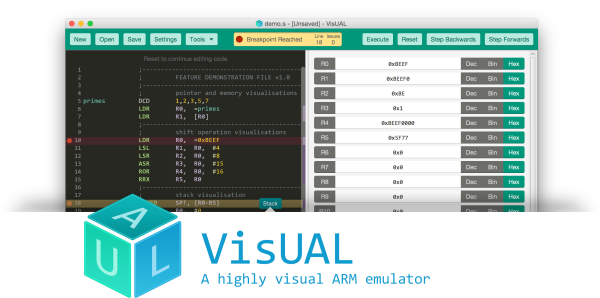
Learning assembly is very important if you want to get a grasp of how a computer truly works under the hood. VisUAL is a very capable ARM emulator for those interested in learning the ARM assembly.

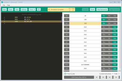
The GUI: A simply program to ADD two numbers

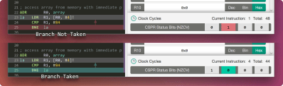
In addition to supporting a large subset of ARM instructions, the CPU is emulated via a series of elaborate and instructive animations that help visualise the flow of data to/from registers, any changes made to flags, and any branches taken. It also packs very useful animations to help grasp some of the more tricky instruction such as shifts and stack manipulations.

As it is was designed specifically to be used as teaching tool at Imperial College London, the GUI is very friendly, all the syntax errors are highlighted, and an example of the correct syntax is also shown.

Branch visualisation, credits: VisUAL homepage

You can also do the usual things you would expect from any emulator, such as single step through execution, set breakpoints, and view data in different bases. It even warns you of any possible infinite loops!

That being said, lugging such an extravagant GUI comes at a price; programs that consume a few hundred thousand cycles hog far too much RAM should be run in the supported headless mode.


34C3: Hacking Into A CPU’s Microcode

Inside every modern CPU since the Intel Pentium fdiv bug, assembly instructions aren’t a one-to-one mapping to what the CPU actually does. Inside the CPU, there is a decoder that turns assembly into even more primitive instructions that are fed into the CPU’s internal scheduler and pipeline. The code that drives the decoder is the CPU’s microcode, and it lives in ROM that’s normally inaccessible. But microcode patches have been deployed in the past to fix up CPU hardware bugs, so it’s certainly writeable. That’s practically an invitation, right? At least a group from the Ruhr University Bochum took it as such, and started hacking on the microcode in the AMD K8 and K10 processors.
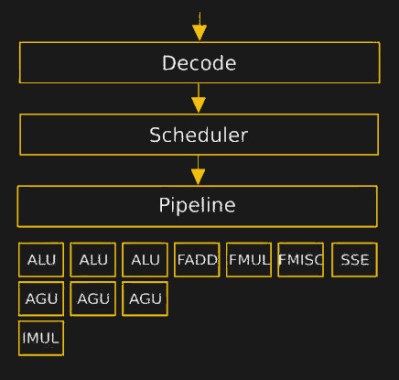
The hurdles to playing around in the microcode are daunting. It turns assembly language into something, but the instruction set that the inner CPU, ALU, et al use was completely unknown. [Philip] walked us through their first line of attack, which was essentially guessing in the dark. First they mapped out where each x86 assembly codes went in microcode ROM. Using this information, and the ability to update the microcode, they could load and execute arbitrary microcode. They still didn’t know anything about the microcode, but they knew how to run it.

So they started uploading random microcode to see what it did. This random microcode crashed almost every time. The rest of the time, there was no difference between the input and output states. But then, after a week of running, a breakthrough: the microcode XOR’ed. From this, they found out the syntax of the command and began to discover more commands through trial and error. Quite late in the game, they went on to take the chip apart and read out the ROM contents with a microscope and OCR software, at least well enough to verify that some of the microcode operations were burned in ROM.

The result was 29 microcode operations including logic, arithmetic, load, and store commands — enough to start writing microcode code. The first microcode programs written helped with further discovery, naturally. But before long, they wrote microcode backdoors that triggered when a given calculation was performed, and stealthy trojans that exfiltrate data encrypted or “undetectably” through introducing faults programmatically into calculations. This means nearly undetectable malware that’s resident inside the CPU. (And you think the Intel Management Engine hacks made you paranoid!)

[Benjamin] then bravely stepped us through the browser-based attack live, first in a debugger where we could verify that their custom microcode was being triggered, and then outside of the debugger where suddenly xcalc popped up. What launched the program? Calculating a particular number on a website from inside an unmodified browser.

He also demonstrated the introduction of a simple mathematical error into the microcode that made an encryption routine fail when another particular multiplication was done. While this may not sound like much, if you paid attention in the talk on revealing keys based on a single infrequent bit error, you’d see that this is essentially a few million times more powerful because the error occurs every time.

The team isn’t done with their microcode explorations, and there’s still a lot more of the command set left to discover. So take this as a proof of concept that nearly completely undetectable trojans could exist in the microcode that runs between the compiled code and the CPU on your machine. But, more playfully, it’s also an invitation to start exploring yourself. It’s not every day that an entirely new frontier in computer hacking is bust open.

An Mbed In Your Browser

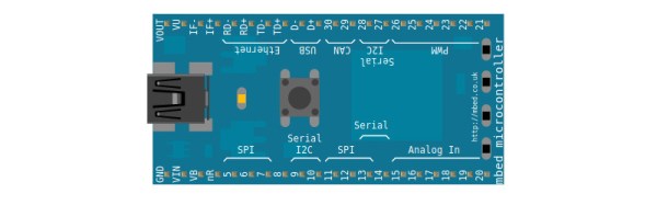
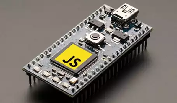
If you have dabbled in the world of ARM microcontrollers, you might be familiar with the Mbed platform, a software abstraction layer for a range of ARM-based small dev boards. If you don’t have an Mbed board but fancy giving it a go, you might imagine that you’d be out of luck, but [Jan Jongboom] could have an answer to your problem in the form of an Mbed simulation in your browser.

We’re not high-end ARM microcontroller developers here at Hackaday so beyond observing that it brings the Mbed abstraction layer binaries to the browser through the magic of Emscripten it’s best to point the curious at its GitHub repository. But we can see its attraction as a means to take a look at Mbed, and given that [Jan] describes himself as “a developer and evangelist currently working on the Internet of Things for ARM“, it’s safe to say this one comes as they say, from the horse’s mouth.

The Mbed board that is probably most famous is the education-focused micro:bit, but there are plenty of others on the market. Back in 2015 we published a getting started guide, if you are new to the Mbed.

Via Hacker News.

Snitch On Your AC Devices With Stolen Power

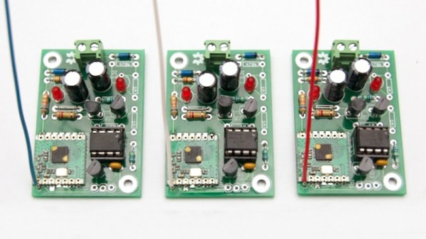
Low power devices are always intriguing, as they open up possibilities for applications with the need to operate remotely, or for very long periods without attention. There are all manner of techniques for powering such devices, too, such as using solar panels, super capacitors, or other fancy devices. The Micro Power Snitch is one such device, which can report wirelessly on your AC-powered appliances.

The device is built around a tiny ARM microcontroller and an RFM69 radio module. The entire circuit is run by leeching power from an AC current transformer, wrapped around one of the power lines of an AC appliance. When an appliance draws over the minimum threshold current (500W on 230VAC, 250W on 115VAC), the device sends a packet out, which can be received and logged at the other end.

The best part of this project, however, is the writeup. The project is split into an 8-part series, breaking down the minutiae of the concepts at work to make this possible. It’s a great primer if you’re interested in designing low-power devices.

We’ve seen some of [jcw]’s power research before – such as this guide to the effects of code on power consumption.

[Thanks to Ronald for the tip!]

DS212 Oscilloscope Review: Open Source And Great For Hacking

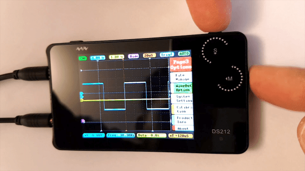
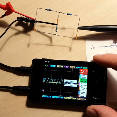
We’ve seen plenty of oscilloscopes that look like repurposed cell phones. Usually, though, they only have one channel. The DS212, has two channels and a signal generator! [Marco] gives his review and a quick tear down in the video below.

The scope isn’t going to replace a big bench instrument, but for a portable scope with a rechargeable battery, it isn’t bad. The 1 MHz analog bandwidth combines with a 10 megasample per second front end and 8K of sample memory. The signal generator can produce basic waveforms up to 1 MHz. We were somewhat surprised the unit didn’t sport a touch screen, which is why you can see [Marco’s] fingers in the screenshot above. He seems to like the dual rotary encoder system the devices uses for navigation.

Where this really stands out is that it is open source for the the firmware running on the STM32 processor inside. We so rarely see this for commercially available bench tools and it makes this a fine hacking platform. It’s easy to imagine adding features like digital signals out and decoding digital data. It would be interesting to marry it with a WiFi chip and use it as a front end for another device over WiFi. Lots of possibilities. [Marco] shows that even though he’s not familiar with the STM32, he was able to add a custom waveform output to the device easily. This has the potential to be a custom troubleshooting platform for your builds. Lining up all of the sensing and signal generation settings for each specific type of test means you don’t need a guru to walk through the common failure modes of a product.

There are many small inexpensive scopes out there that might not match a big bench instrument but can still be plenty useful. [Jenny List] just reviewed one that comes in at around $21. And last year, we saw a sub-$100 scope that would net you just one channel scope. That’s progress!

Build One, Get Two: CPLD And STM32 Development On A Single Board

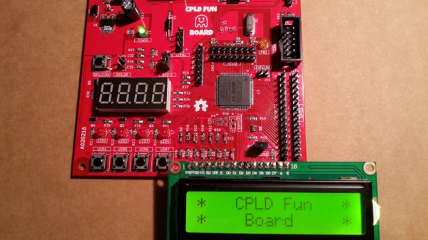
Programmable logic devices have claimed their place in the hobbyist world, with more and more projects showing up that feature either a CPLD or their bigger sibling, the FPGA. That place is rightfully earned — creating your own, custom digital circuitry not only adds flexibility, but opens up a whole new world of opportunities. However, this new realm can be overwhelming and scary at the same time. A great way to ease into this is combining the programmable logic with a general purpose MCU system that you already know and are comfortable with. [Just4Fun] did just that with the CPLD Fun Board, a development board connecting an Arduino compatible STM32F103 Cortex-M3 controller to an Altera MAX II CPLD.

The PCB itself has some standard development board equipment routed to the CPLD: LEDs, buttons, a seven-segment display, and additional GPIO. The rest of the CPLD’s pins are going straight to the STM32 and its SPI, I2C and UART pins. Let’s say you want to create your own SPI device. With the CPLD Fun Board, you can utilize all the pre-existing libraries on the STM32 and fully focus on the programmable logic part. Better yet, every connection from MCU to CPLD has its own pin header connection to attach your favorite measurement device for debugging. And in case you’re wondering — yes, you can attach external hardware to those connectors by setting either MCU or CPLD pins to Hi-Z.

The downside of all this is the need for proprietary design software and a dedicated programmer for the CPLD, which sadly is the everyday reality with programmable logic devices. [Just4Fun] did a great job though writing up a detailed step-by-step tutorial about setting up the environment and getting started with the board, but there are also other tutorials on getting started with CPLDs out there, in case you crave more.

DIY Laptop Aims For Complete Hardware Freedom

Open source software has unquestionably gone from fringe idealism to mainstream, even if the average person doesn’t really know it. From their web browser to their smartphone operating system, more people are running open source software today than at any other time in the history of computing, and the numbers are only getting bigger. While we can debate how well some companies are handling their responsibilities to the open source community, overall this is probably a lot closer to an open source utopia that many of us ever believed we’d get.

For argument’s sake, let’s say the software is settled. What’s next? Well, if we’ve got all the open source software we could ever ask for, naturally we now need to run it on open source hardware. Just like our software, we want to see how it works, we want to modify it, and to fix it ourselves if we want. These goals are precisely what [Lukas Hartmann] had in mind when he started work on Reform, the latest entry in the world of fully open source laptops.

A plate of fresh keycaps

Like the Novena that came before it, the Reform leverages the four-core ARM Cortex-A9 NXP i.MX6 SoC to deliver tablet-level performance, though [Lukas] mentions the design may migrated to the upgraded six-core version of the chip in the future which should give it a little more punch. The SoC is paired with the Vivante GC2000 GPU which can be used under Linux without any binary blobs. Most hardware is connected to the system via the USB 2.0 bus, though networking is provided by a ThinkPenguin mini PCI-e wireless adapter, and on-board SATA handles the 128 GB SSD.

While the internals are relatively run-of-the-mill these days, the work that [Lukas] has done on the case and input devices is definitely very impressive. He partnered with industrial designer [Ana Dantas] to get the look and feel of the system down, and built almost everything out of 3D printed parts. Even the keyboard caps and the trackball were manufactured in house on a Formlabs Form 2. Rather than using an off-the-shelf USB HID solution, [Lukas] is using Teensy LC boards to interface the custom input hardware with the OS.

[Lukas] is still working on how and when the Reform will be made available to the public. After some refinements, the team hopes to make both kits and individual parts available, and of course put all the files up so you can build your own if you’ve got the equipment. A mockup Amazon listing for the Reform has been posted to get the public’s feedback on the look and features of the machine, and [Lukas] asks that anyone with comments and suggestions send him an email.

Between the Reform, Novena, and the Olimex, competition in the realm of DIY laptops is frankly staggering. Now we just need more people working on open hardware smartphones.

Thanks to [Adrian] for the tip.