One of the primary issues with EVs is that you need to pull over and stop to get a charge. If there isn’t a high-speed DC charger available, this can mean waiting for hours while your battery tops up.
It’s been the major bugbear of electric vehicles since they started hitting the road in real numbers. However, a new wireless charging setup could allow you to juice up on the go.
Electric Highways
Over the years, many proposals have been made to power or charge electric vehicles as they drive down the road. Many are similar to the way we commonly charge phones these days, using inductive power transfer via magnetic coils. The theory is simple. Power is delivered to coils in the roadway, and then picked up via induction by a coil on the moving vehicle.
Taking these ideas from concept into reality is difficult, though. When it comes to charging an electric vehicle, huge power levels are required, in the range of tens to hundreds of kilowatts. And, while a phone can sit neatly on top of a charging pad, EVs typically require a fair bit of ground clearance for safely navigating the road. Plus, since cars move at quite a rapid pace, an inductive charging system that could handle this dynamic condition would require huge numbers of coils buried repeatedly into the road bed. Continue reading “Coils In The Road Could Charge EVs While Driving”→
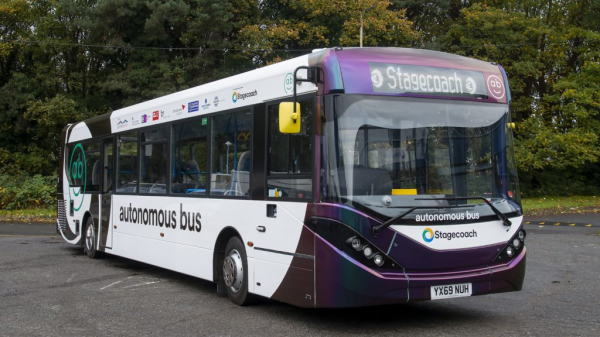
Known as Project CAVForth for the UK government’s Center for Connected and Autonomous Vehicles (CCAV) and the Forth bridge, over which the buses will travel, it is said to be the most complex test of autonomous on-road mass transit yet undertaken in Europe. The full-size single-deck motorcoaches, five in total, will ply a 22-km (14-mile) route into Edinburgh from Fife, crossing the famous Firth of Forth on the Forth Road suspension bridge. The buses will carry about 36 passengers each and run at SAE Level 4 autonomy, meaning that a safety driver is optional under good driving conditions. Continue reading “Automate The Freight: Autonomous Buses To Start Operation In UK”→
Imagine you’re sending a piece of hardware to space on a satellite. Unless you’re buddy-buddy with NASA, it’s pretty unlikely you’ll ever be able to head up there and fix something if it goes wrong once it’s launched. Robust design is key, so that even in the event of a failure in one component, the rest of the hardware can keep working.
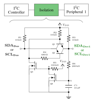
The example I2C isolation circuit from [Max’s] paper. The SPI implementation is even simpler.[Max Holliday] found himself in this exact situation, running 69 I2C and SPI devices in a single satellite. Thus, he came up with circuits to auto-isolate devices from these buses in the event of an issue. That work is the subject of a research paper now available on the TechRxiv Preprint Server.
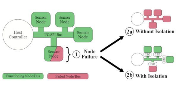
The problem is that these simple buses aren’t always the most robust, being vulnerable to single-point failures where one bad part takes down other parts of the bus. [Max] notes that vast numbers of sensors and devices rely on these standards, and it can be difficult or prohibitively expensive to design without them, so a solution was needed.
To fix this, [Max] developed a simple external circuit that could be placed on each node of a I2C or SPI communication bus. In the event of malfunction, that node can be cut off from the bus by this circuit, allowing the rest of the system to go on functioning.
With little more than a few transistors, MOSFETs and passives, you too could protect your buses from malfunctions using these techniques. [Max] did just that on the NASA V-R3x mission which flew successfully in January 2021 if you needed any further confirmation of the value of this technique.
It’s something that won’t bother the home hobbyist building a garage door opener, but it could be of great value to those designing systems that must fail gracefully if they fail at all. Be sure to share your best tips and tricks for robust SPI and I2C buses in the comments below!
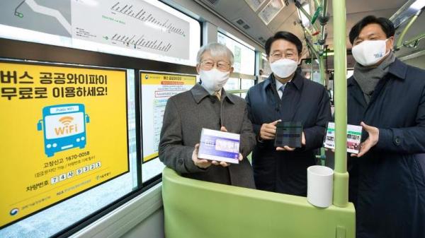
Previously, subscriber-based WiFi had been installed on subways and in subway stations. It was provided privately by two phone carriers and free only for their subscribers. The coverage was spotty and slow, and in 2017 the government took over and implemented a better system. With this announcement, the whole public transportation system is now covered with stable and free WiFi.
We also noticed that the government has released the details of the 220,000 WiFi access points to the public. This includes the location, IP address, and RSSI data for use by people and companies wanting to develop location-based services. What is the state of free WiFi access points in your region, and does it extend to public transportation? Do you find it reliable, or do you use your data plan when out and about?
Around the world, governments and city planners have long struggled with the issue of transport. Getting people where they need to be in a timely fashion is key to making a city a comfortable, attractive place to live. As far as public transport is concerned, this typically consists of buses on the roads, and trams and trains on rails.
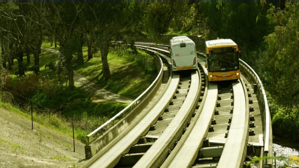
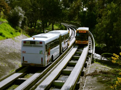
Down in the city of Adelaide, Australia, things get a little muddled, however. Nestled in a river valley lies a special transportation network known as the O-Bahn, where buses ride on concrete rails and the drivers can even take their hands off the wheel. The system remains a rarity worldwide, and was spawned by a perfect storm of conflicting requirements.
A Child of Circumstance
In the 1970s, the South Australian government found itself backed into a corner. Facing a booming population in the north-eastern suburbs, new transport links with greater capacity were needed to get people to the central business district. Original plans from the 1960s had called for more freeways to be built all over the city to solve the problem. In the face of stiff public opposition, legislation was passed in 1970 blocking the construction of any new freeways for a full decade, forcing the government to consider alternatives.
O-Bahn buses passing at speed near Stephens Terrace. Buses formerly reached speeds up to 100 km/h on the network; this was dropped to 85 km/h in 2012, adding 20 seconds to the average run. Credit: Lewin Day
Despite plans being shelved, a corridor of land stretching from the city to the north-east had already been acquired for freeway construction. This was retained, and studies were commissioned to determine the best transportation solution to suit the needs of the area. The “North East Adelaide Public Transport Review” suggested light-rail or a busway would be the best solution.
Initial plans were proposed to link the north-east with a light-rail tramway that would connect with the existing tramline from the city proper to Glenelg in the west. However, the City of Adelaide protested the plan, believing that extending the existing tramline to the east would damage the city’s carefully planned structure. Plans were made to rectify this by running part of the line underground, massively increasing costs, and the proposal was shelved.
It was at this time, the guided busway in Essen, Germany came to the attention of the state government. Aiming to help reduce congestion by allowing buses to share tram tunnels, it began as a demonstration which later developed into the Spurbus network. The system offered lower cost and higher flexibility than light rail, and avoided the need to carve up the city to hook in to the existing light rail network. Had Adelaide laid out its existing heavy or light rail networks differently, the O-Bahn might not have gotten a look in. However, back in the early 1980s, it was an easy solution in a sea of difficult choices.
If you’re a frequent traveler on a public transit system, it can be helpful to know when the trains or buses are arriving and if there are any delays. We might reach for a tablet to mount on the wall, but that relies on keeping the OS, the software, and its library dependancies up to date. For true reliability you’ll need to build directly in hardware, which is exactly what this map of the London tube system uses.
The base map is printed directly on PCB, with LEDs along each of the major routes to indicate the current location of the trains. A few small chips handle the WiFi connection — it appears to our eye to be an ESP8266 — and pulling the information about the trains from the London Underground API (it would be virtually impossible to build everything for this project in hardware). The hardware can be easily reprogrammed, and with the PCB layout this could be adapted for other public transit fairly easily.
Even apart from the philosophical differences on design between hardware and software approaches, we still appreciate the aesthetic of LEDs on PCB. In fact, we’ve seen a whole host of artwork on PCBs ever since the price came down dramatically in the past two decades.
Before I got a license and a car, getting to and from high school was an ordeal. The hour-long bus ride was awful, as one would expect when sixty adolescents are crammed together with minimal supervision. Avoiding the realities going on around me was a constant chore, aided by frequent mental excursions. One such wandering led me to the conclusion that we high schoolers were nothing but cargo on a delivery truck designed for people. That was a cheery fact to face at the beginning of a school day.
What’s true for a bus full of students is equally true for every city bus, trolley, subway, or long-haul motorcoach you see. People can be freight just as much as pallets of groceries in a semi or a bunch of smiling boxes and envelopes in a brown panel truck. And the same economic factors that we’ve been insisting will make it far more likely that autonomous vehicles will penetrate the freight delivery market before we see self-driving passenger vehicles are at work with people moving. This time on Automate the Freight: what happens when the freight is people?