Fail Of The Week: The Arduino Walkie That Won’t Talkie

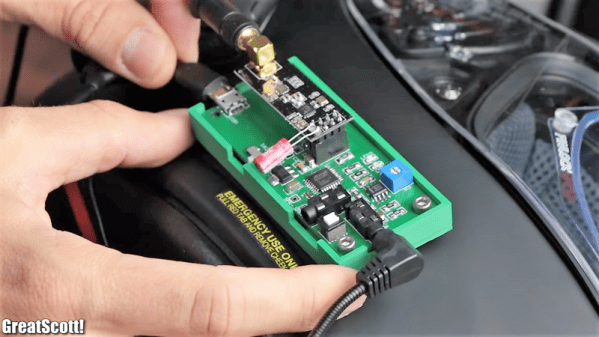
There’s something seriously wrong with the Arduino walkie-talkie that [GreatScott!] built.

The idea is simple: build a wireless intercom so a group of motor scooter riders can talk in real-time. Yes, such products exist commercially, but that’s no fun at all. With a little ingenuity and a well-stocked parts bin, such a device should be easy to build on the cheap, right?

Apparently not. [GreatScott!] went with an Arduino-based design, partly due to familiarity with the microcontroller but also because it made the RF part of the project seemingly easier due to cheap and easily available nRF24 2.4 GHz audio streaming modules. Everything seems straightforward enough on the breadboard – an op-amp to boost the signal from the condenser mic, a somewhat low but presumably usable 16 kHz sampling rate for the ADC. The radio modules linked up, but the audio quality was heavily distorted.

[GreatScott!] assumed that the rat’s nest of jumpers on the breadboard was to blame, so he jumped right to a PCB build. It’s a logical step, but it seems like it might be where he went wrong, because the PCB version was even worse. We’d perhaps have isolated the issue with the breadboard circuit first; did the distortion come from the audio stage? Or perhaps did the digitization inject some distortion? Or could the distortion be coming from the RF stage? We’d want to answer a few questions like that before jumping to a final design.

We love that [GreatScott!] has no issue with posting his failures – we’ve covered his suboptimal CPU handwarmer, and his 3D-printed BLDC motor stator was a flop too. It’s always nice to post mortem these things to avoid a similar fate.

Continue reading “Fail Of The Week: The Arduino Walkie That Won’t Talkie”

DIY Vactrols Give MIDI-Controlled Video Distortion

It’s one thing to assemble your own circuits from scratch using off the shelf components. It’s quite another to build the components first, and then build the circuit.

That’s the path [Joris Wegner] took with this video distortion effects box, dubbed PHOSPHOR. One might wonder why you’d want a box that makes a video stream look like playback from a 1980s VHS player with tracking problems, but then again, audio distortion for artistic effect is a thing, so why not video? PHOSPHOR is a USB MIDI device, and therein lies the need for custom components. [Joris] had a tough time finding resistive optoisolators, commonly known as Vactrols and which are used to control the distortion effects. He needed something with a wide dynamic range, so he paired up a bright white LED and a cadmium sulfide photoresistor inside a piece of heat shrink tubing. A total of 20 Vactrols were fabricated and installed on a PCB with one of the coolest silkscreens we’ve ever seen, along with the Sparkfun Pro Micro that takes care of MIDI chores. Now, distortions of the video can be saved as presets and played back in sync with music for artistic effects.

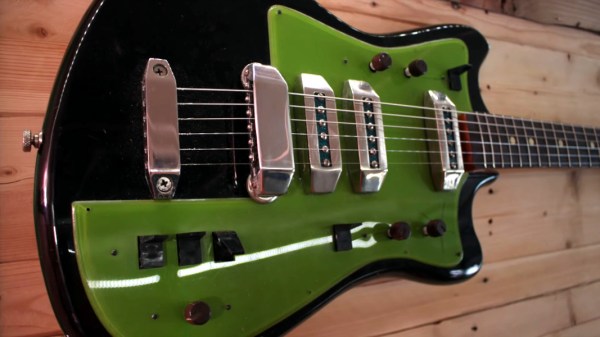
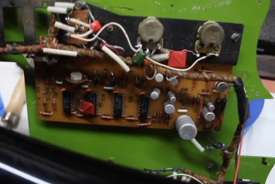
This isn’t the first time Vactrols have made an appearance here, of course. We saw them a while back with this Arduinofied electric guitar, and more recently with a triple-555 timer synth.

Continue reading “DIY Vactrols Give MIDI-Controlled Video Distortion”

OptoGlitch Is An Optocoupler Built For Distortion

When we are concerned with the accurate reproduction of a signal, distortion and noise are the enemy that engineers spend a great deal of time eliminating wherever possible. However, humans being the imperfect creatures that we are, we sometimes desire a little waviness and grain in our media – typically of the analog variety, as the step changes of digital distortion can be quite painful. Tired of Instagram filters and wanting to take a different approach, [Patrick Pedersen] built the OptoGlitch – a hardware solution for analog distortion.

Changing the number of samples per pixel varies the accuracy of reproduction of the original image, left.

The concept of operation is simple – pixel values of a digital image are sent out by varying the intensity of an LED, and are then picked up by a photoresistor and redigitized. The redigitized image then bears a variety of distortion and noise effects due to the imperfect transmission process.

In the OptoGlitch hardware, the LED and photoresistor are intentionally left open to ambient light to further allow noise and distortion to happen during the transmission process. A variety of calibration methods are used to avoid the results being completely unrecognizable, and there are various timing and sampling parameters that can be used to alter the strength of the final effect.

It’s possible to introduce distortion more intentionally, too – such as this project that hides metadata in malformed glyphs.

A Guide To Audio Amps For Radio Builders

For hams who build their own radios, mastering the black art of radio frequency electronics is a necessary first step to getting on the air. But if voice transmissions are a goal, some level of mastery of the audio frequency side of the equation is needed as well. If your signal is clipped and distorted, the ham on the other side will have trouble hearing you, and if your receive audio is poor, good luck digging a weak signal out of the weeds.

Hams often give short shrift to the audio in their homebrew transceivers, and [Vasily Ivanenko] wants to change that with this comprehensive guide to audio amplifiers for the ham. He knows whereof he speaks; one of his other hobbies is jazz guitar and amplifiers, and it really shows in the variety of amps he discusses and the theory behind them. He describes a number of amps that perform well and are easy to build. Most of them are based on discrete transistors — many, many transistors — but he does provide some op amp designs and even a design for the venerable LM386, which he generally decries as the easy way out unless it’s optimized. He also goes into a great deal of detail on building AF oscillators and good filters with low harmonics for testing amps. We especially like the tip about using the FFT function of an oscilloscope and a signal generator to estimate total harmonic distortion.

The whole article is really worth a read, and applying some of these tips will help everyone do a better job designing audio amps, not just the hams. And if building amps from discrete transistors has you baffled, start with the basics: [Jenny]’s excellent Biasing That Transistor series.

[via Dangerous Prototypes]

Vintage Organ Donates Parts For Two New Instruments

It’s often hard to know what to do with a classic bit of electronics that’s taking up far too much of the living room for its own good. But when the thing in question is an electronic organ from the 1970s, the answer couldn’t be clearer: dissect it for its good parts and create two new instruments with them.

Judging by [Charlie Williams]’ blog posts on his Viscount Project, he’s been at this since at least 2014. The offending organ, from which the project gets its name, is a Viscount Bahia from the 1970s that had seen better days, apparently none of which included a good dusting. With careful disassembly and documentation, [Charlie] took the organ to bits. The first instrument to come from this was based on the foot pedals. A Teensy and a custom wood case turned it into a custom MIDI controller; hear it in action below. The beats controller from the organ’s keyboard was used for the second instrument. This one appears far more complex, not only for the beautiful, hand-held wooden case he built for it, but because he reused most of the original circuitry. A modern tube amp was added to produce a little distortion and stereo output from the original mono source, with the tip of the tube just peeking above the surface of the instrument. We wish there were a demo video of this one, but we’ll settle for gazing at the craftsmanship.

In a strange bit of timing, [Elliot Williams] (no relation, we assume) just posted an Ask Hackaday piece looking for help with a replacement top-octave generator for another 1970s organ. It’s got a good description of how these organs worked, if you’re in the mood to learn a little more.

Continue reading “Vintage Organ Donates Parts For Two New Instruments”

Taking A Guitar Pedal From Concept Into Production

Starting a new project is fun, and often involves great times spent playing with breadboards and protoboards, and doing whatever it takes to get things working. It can often seem like a huge time investment just getting a project to that functional point. But what if you want to take it to the next level, and take your project from a prototype to a production-ready form? This is the story of how I achieved just that with the Grav-A distortion pedal.

Why build a pedal, anyway?

The author, shown here with bandmates.

A long time ago, I found myself faced with a choice. With graduation looming on the horizon, I needed to decide what I was going to do with my life once my engineering degree was squared away. At the time, the idea of walking straight into a 9-5 wasn’t particularly attractive, and I felt like getting back into a band and playing shows again. However, I worried about the impact an extended break would have on my potential career. It was then that I came up with a solution. I would start my own electronics company, making products for musicians. Continue reading “Taking A Guitar Pedal From Concept Into Production”

I Think I Failed. Yes, I Failed.

Down the rabbit hole you go.

In my particular case I am testing a new output matching transformer design for an audio preamplifier and using one of my go to driver circuit designs. Very stable, and very reliable. Wack it together and off you go to test and measurement land without a care in the world. This particular transformer is designed to be driven with a  class A amplifier operating at 48 volts in a pro audio setting where you turn the knobs with your pinky in the air sort of thing. Extra points if you can find some sort of long out of production parts to throw in there for audiophile cred, and I want some of that.

img_2857-2Lets use some cool retro transistors! I merrily go along for hours designing away. Carefully balancing the current of the long tailed pair input. Picking just the right collector power resistor and capacitor value to drive the transformer. Calculating the negative feedback circuit for proper low frequency cutoff and high frequency stability, and into the breadboard the parts go — jumper clips, meter probes, and test leads abound — a truly joyful event.

All of the voltages check out, frequency response is what you would expect, and a slight tweak to the feedback look brought everything right into happiness. Time to fire up the trusty old HP 334A Distortion Analyzer. Those old machines require you to calibrate the input circuit and the volt meter, tune a filter to the fundamental frequency you are applying to the device under test and step down to lower and lower orders of distortion levels until the meter happily sits somewhere in the middle of a range.

Most modern circuits in even cheap products just go right down to sub .1% total harmonic distortion levels without even a thought and I expected this to be much the same. The look of horror must have been pronounced on my face when the distortion level of my precious circuit was something more akin to a clock radio! A frantic search began. Was it a bad jumper, or a dirty lead in the breadboard, or an unseated component? Was my function generator in some state of disrepair? Is the Stephen King story Maximum Overdrive coming true and my bench is going to eat me alive? All distinct possibilities in this state of panic.

Continue reading “I Think I Failed. Yes, I Failed.”