Homemade Test Jig Is Cheaper Than Outsourcing

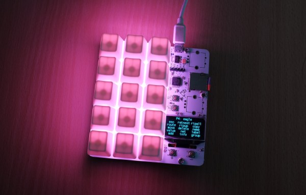
In the past, [Sjaak] has had his testing and programming jigs made for him in Shenzhen, but realized they weren’t that great of a value. They weren’t terribly expensive in the grand scheme of things, but they didn’t include any wiring, so he was still spending his own time and money. His quest to develop his own in-house jigs not only netted him a considerable cost savings in the end, but also produced a nicely detailed post on his site for anyone else who may be heading down the same path. That’s a win-win in our book.

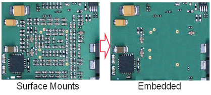
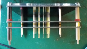
The idea behind a jig is pretty simple: essentially it’s just a mount that holds the PCB, and a set of pins which contact the appropriate points on the board. The jig can then provide power, programming, status LEDs for testing, etc. Basically anything that you can’t or don’t want to include on the final board, but will help in testing or programming them.

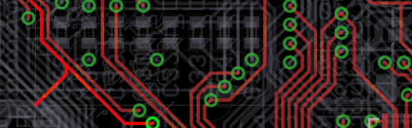
To start, [Sjaak] begins with a blank PCB in Eagle and imports his target board. With the two lined up, he can then mark where he wants the pins to go on the jig, and add labels to the silkscreen to make things a little easier during diagnostics. The target board is then removed, the file converted to Gerber, and it’s sent off for manufacturing. With a few more tweaks, the file is then exported to DXF and laser cut out of acrylic. When the PCBs come back, it’s just a matter of sandwiching it all together with some standoffs and adding the pins.

[Sjaak] mentions that he was inspired by an old post on how SparkFun was internally handling their test jigs, though we think with a dash of automation he could make things even easier for himself.

An Awesome Open Mechanical Keyboard

Who doesn’t want a little added functionality to their  lives? Feeling a few shortcut keys would make working in Eagle a bit smoother, [dekuNukem] built his own programmable mechanical keypad: kbord.

It sports vibrant RGB LED backlight effects with different animations, 15 keys that execute scripts — anything from ctrl+c to backdoors — or simple keystrokes, up to 32 profiles, and a small OLED screen to keep track of which key does what!

kbord is using a STM32F072C8T6 microcontroller for its cost, speed, pins, and peripherals, Gateron RGB mechanical keys — but any clear key and keycaps with an opening for the kbord’s LEDs will do — on a light-diffusing switch plate, and SK6812 LEDs for a slick aesthetic.

Check out the timelapse video tour of his build process after the break! (Slightly NSFW, adolescent humor for a few seconds of the otherwise very cool video. Such is life.)

Continue reading “An Awesome Open Mechanical Keyboard”

How To Do PCB Art In Eagle

Last month I had the pleasure of creating a new piece of hardware for Tindie. [Jasmine], the queen bee of Tindie, and I designed, developed, and kitted three hundred Tindie badges in ten days leading up to DEF CON. The badges were a complete success, they introduced soldering to a lot of people, and were loved by all.

This badge was such a rousing success, it’s now official Tindie swag. We’ll be handing out a few of these blinky badges at upcoming events. But as of right now we’ve already handed out our entire stock, that means we need to build more. The second run meant ordering a thousand PCBs.

We could just do another run, and order a few more PCBs from the Gerbers I’ve already designed. I’m not really happy with the first version of this badge, though, and this is an opportunity to improve my design. This also gives me an opportunity to demonstrate my workflow for creating artistic boards in Eagle.

Effectively, what I’ll be demonstrating here is the creation of the Benchoff Nickel. A few months ago, [Andrew Sowa] took a portrait of yours truly, changed the colors to what is available on a normal OSHPark PCB, and turned that into different layers in KiCad. There are a few differences here. Firstly, I’ll be using a blue solder mask, although the same technique can be applied to green, red, yellow, white, or black soldermask. Secondly, this is Eagle, and I’m going to do the majority of the work with a BMP import. This is the fast and easy way to do things; if you want a KiCad tutorial, check out [Andrew]’s work, or my overly-involved multiple silkscreen process for KiCad. I don’t recommend this overly-involved process if you can help it. It took 20 hours to do the art for my previous project in KiCad, and I estimate it would have taken two in Eagle.

With that said, here’s the easy, cheap, and fast way of doing artistic boards in Eagle.

Continue reading “How To Do PCB Art In Eagle”

New Release Makes EAGLE And Fusion 360 Besties

The latest release of EAGLE builds a bridge between mechanical design and electronic design. Version 8.3 rolls in the ability to synchronize between EAGLE and Fusion 360. You can now jump between mechanical design and PCB layout without the need for extra steps in between. This is the first release of EAGLE that highlights what the Autodesk purchase actually means.

Just over a year ago, Autodesk bought EagleCAD which is one of the more popular PCB design suites for students, electronic hobbyists, and Open Hardware engineers. While there were some questions about the new license structure of EAGLE under the Autodesk banner, there was a promise of a faster development schedule and the possibility for integration of EAGLE with Autodesk’s CAD programs. Now it’s finally time for EAGLE and Fusion 360 to become besties.

The EAGLE and Fusion 360 integration update includes an online library editor with managed libraries. These online libraries are the ‘cloud’ solution to a folder full of custom EAGLE libraries filled with parts. These libraries package 3D models with the EAGLE libraries, simplifying mechanical design. You can place components on your PCB, then pull that layout into Fusion 360 to see how the board will work with your enclosure. Component placements that collide with the enclosure can be adjusted in Fusion before jumping back to EAGLE to fix the routing.

Embedded passive designs. The resistors *are* the PCB.

There are a few other interesting items in the release notes for EAGLE 8.3. At the top of the list is a new ‘board shape’ object. This is more than just a milling layer for a board outline — the board shape object can now be checked with DRC to ensure components aren’t too close to an edge. This also allows for new features like customizable cutouts and embedded passive designs, or putting resistors and caps in the layers of a PCB instead of placing them as discrete components.

With this release, there is a new Single Layer Mode. This mode only highlights the active layer of the PCB, leaving all other layers grayed out. To be honest, this feature should have been in EAGLE ten years ago, but late is better than never.

For the last year, those of us not complaining about the new EAGLE licensing situation have been watching the updates to EAGLE creep out of Autodesk. There has been a lot of speculation on what Autodesk would bring to the table when it comes to electronic design. This is it. It looks like Autodesk is fulfilling their promise to integrate electronic and mechanical design. The latest EAGLE release looks great, especially with the addition of walk-around routing and something resembling push and shove traces added earlier this year, combined with this update for the mechanical side of design projects.

You can check out a promo video from Autodesk of the new EAGLE release below.

Continue reading “New Release Makes EAGLE And Fusion 360 Besties”

Laser Cut Enclosures From Eagle Files

Once a project is finished, it might still need a decent enclosure. While it’s possible to throw a freshly soldered PCB in a standard enclosure, or piece of Tupperware, or cardboard box, these options don’t have the fit and finish of something custom-made. If you have a laser cutter sitting around, it’s a simple matter to cut your own enclosure, but now that process is much easier thanks to [Ray]’s latest project.

Since [Ray] was already using Eagle to design his PCBs, it seemed like a short step to using the Eagle files to design the enclosure as well. The script runs from those files and creates everything necessary to send to the laser cutter for manufacturing. Right now, [Ray] points out that the assembly time for each enclosure can be high, and this method might not be suited for large numbers of enclosures. Additionally, some of the calculations still need to be done by hand, but there are plans to automate everything in the future.

For single projects, though, this script could cut a lot of time off of designing an enclosure and building it from scratch, and could also help improve aesthetics over other options like 3D printed enclosures. Of course, if you have a quality 3D printer around but no laser cutter, there are options for custom enclosures as well.

DIY Shortcut Keyboard

Working with CAD programs involves focusing on the task at hand and keyboard shortcuts can be very handy. Most software packages allow the user to customize these shortcuts but eventually, certain complex key combination can become a distraction.

[awende] over at Sparkfun has created a Cherry MX Keyboard which incorporates all of the Autodesk Eagle Shortcuts to a single 4×4 matrix. The project exploits the Arduino Pro Mini’s ability to mimic an HID device over USB thereby enabling the DIY keyboard. Pushbuttons connected to the GPIOs are read by the Arduino and corresponding shortcut key presses are sent to the host machine.

Additional functionality is implemented using two rotary encoders and the Teensy encoder library. The first knob functions as a volume control with the push-button working as a mute button. The encoder is used to control the grid spacing and the embedded button is used to switch between imperial and metric units. The entire code, as well as the schematic, is available on GitHub for your hacking pleasure. It’s a polished project just ready for you to adapt.

The project can be extended to be used with other computer software such as Gimp and the keys may be replaced by capacitive touch sensors making it more sturdy. Bluetooth can be added to make things wireless and you can check out the Double Action Keyboard to extend functionality further. Continue reading “DIY Shortcut Keyboard”

A LED Strip Clock As Linear As Time

We love custom clocks here at Hackaday, and are always thrilled to see each inventive means of time-keeping. In a seldom-seen take on the familiar device, the [Bastel Brothers]’s LED Strip Clock’s sleek profile finds itself in good company.

The clock is a two-metre strip of 60 LEDs; every minute past the current hour corresponds to one lit LED, every fifth LED is turned to red in order to make reading minutes easier. So 3 red LEDs +3 green LEDs=18 minutes, with the hour marked by a third color. Sounds complex, but the [Brothers] are quick to say you get used to it quickly, especially when the 6 o’clock LED is centered at some noticeable object or feature.

Continue reading “A LED Strip Clock As Linear As Time”