Vibrating Distance Torch Illuminates The Dark Without Light

If you’ve ever had to move around in a dark room before, you know how frustrating it can be. This is especially true if you are in an unfamiliar place. [Brian] has attempted to help solve this problem by building a vibrating distance sensor that is intuitive to use.

The main circuit is rather simple. An Arduino is hooked up to both an ultrasonic distance sensor and a vibrating motor. The distance sensor uses sound to determine the distance of an object by calculating how long it takes for an emitted sound to return to the sensor. The sensor uses sounds that are above the range of human hearing, so no one in the vicinity will hear it. The Arduino then vibrates a motor quickly if the object is very close, or slowly if it is far away. The whole circuit is powered by a 9V battery.

The real trick to this project is that the entire thing is housed inside of an old flashlight. [Brian] used OpenSCAD to design a custom plastic mount. This mount replaces the flashlight lens and allows the ultrasonic sensor to be secured to the front of the flashlight. The flashlight housing makes the device very intuitive to use. You simply point the flashlight in front of you and press the button. Instead of shining a bright light, the flashlight vibrates to let you know if the way ahead is clear. This way the user can more easily navigate around in the dark without the risk of being seen or waking up people in the area.

This reminds us of project Tacit, which used two of these ultrasonic sensors mounted on a fingerless glove.

Remote Tester

A Simple Circuit For Testing Infrared Remote Controls

Every now and then a remote control acts up. Maybe you are trying to change the channel on your television and it’s just not working. A quick way to determine if the remote control is still working is by using a cell phone camera to try to see if the IR LED is still lighting up. That can work sometimes but not always. [Rui] had this problem and he decided to build his own circuit to make it easier to tell if a remote control was having problems.

The circuit uses a Vishay V34836 infrared receiver to pick up the invisible signals that are sent from a remote control. A Microchip 12F683 processes the data and has two main output modes. If the remote control is receiving data continuously, then a green LED lights up to indicate that the remote is functioning properly. If some data is received but not in a continuous stream, then a yellow LED lights up instead. This indicates that the batteries on the remote need to be replaced.

The circuit also includes a red LED as a power indicator as well as RS232 output of the actual received data. The PCB was cut using a milling machine. It’s glued to the top of a dual AAA battery holder, which provides plenty of current to run the circuit.

Meter Backlight

Adding A Backlight To A Cheap Multimeter

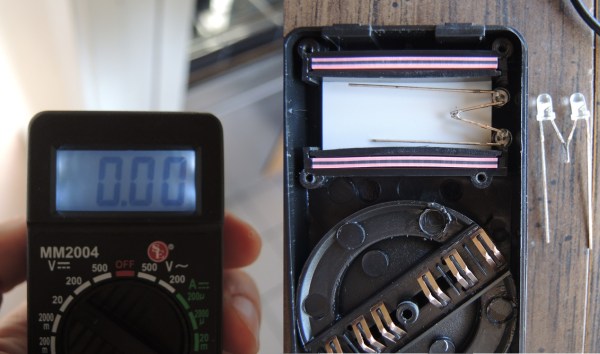
We don’t all need super high quality electronic testing gear. Sometimes second-hand or inexpensive equipment is accurate enough to get the job done. Though it can be a bit annoying to miss out on some of those “luxury” features. [Ekriirke] had this problem with his cheap multimeter. He wished the LCD screen had a backlight for easier visibility, so rather than upgrade to a more expensive unit he just added one himself.

After opening up the multimeter [Ekriirke] found that it ran on a single 12V battery. He realized that the simplest thing to do would be to wire up four white LEDs in series. The four LEDs were arranged within the case off to each side of the LCD, one in each corner. The leads were bent at 90 degree angles and soldered together “dead bug” style. Thin strips of copper foil tape were attached to the PCB in such a way that the anode and cathode from the LEDs would make contact when the case was closed back up.

The tape wraps around to the other side of the PCB where there was more room for the next piece of the circuit. A capacitor, resistor, and transistor are used in conjunction with a momentary switch. This circuit allows [Ekriirke] to turn on the light for about ten seconds by pressing the button one time. The circuit also runs through the meter’s dial switch, preventing the LEDs from being turned on while the meter itself is turned off.

[via Reddit]

Embedding PCBs In 3D Prints

The folks over at Lunchbox Electronics are working on a very cool prototype: embedding LEDs inside standard 1×1 Lego bricks. Being a prototype, they needed a cheap way to produce Lego bricks stuffed with electronics. It turns out a normal 3D printer has okay-enough resolution, but how to put the electronics in the bricks? Gcode wizardry, of course.

3d-printed-LEGO-w-pcb-thumbThe electronics being stuffed into the bricks isn’t much – just a small PCB with an LED. It does, however, need to get inside the brick. This requires stopping the 3D printer at the right layer, moving the print head out of the way, inserting the PCB, and moving the head back to where it stopped.

Gcode to the rescue. By inserting a few lines into the Gcode of the print, the print can be paused, the print head raised and returned, and the print continued.

If you want to check out what these light up Lego look like, There’s a Kickstarter happening now. It’s exactly what the 80s space sets needed, only thirty years late.

From Gates To FPGA’s – Part 1: Basic Logic

It’s time to do a series on logic including things such as programmable logic, state machines, and the lesser known demons such as switching hazards. It is best to start at the beginning — but even experts will enjoy this refresher and might even learn a trick or two. I’ll start with logic symbols, alternate symbols, small Boolean truth tables and some oddball things that we can do with basic logic. The narrative version is found in the video, with a full reference laid out in the rest of this post.

Invert

1The most simple piece of logic is inversion; making a high change to low or a low change to high. Shown are a couple of ways to write an inversion including the ubiquitous “bubble” that we can apply almost anywhere to imply an inversion or a “True Low”. If it was a one it is now a zero, where it was a low it is now a high, and where it was true it is now untrue.

AND

2Moving on to the AND gate we see a simple truth table, also known as a Boolean Table, where it describes the function of “A AND B”. This is also our first opportunity to see the application of an alternate symbol. In this case a “low OR a low yields a low”

NAND

3Most if not all of the standard logic blocks come in an inverted form also such as the NAND gate shown here. The ability to invert logic functions is so useful in real life that I probably used at least three times the number of NAND gates as regular AND gates when doing medium or larger system design. The useful inversion can occur as spares or in line with the logic.

Continue reading “From Gates To FPGA’s – Part 1: Basic Logic”

Plant Watering System

Automated Plant Watering System Uses Car Parts

[Shane] recently built an automated plant watering system for his home. We’ve seen several similar projects before, but none of them worked quite like this one. Shane’s system is not hooked into the house plumbing and it doesn’t use any off-the-shelf electronic valves.

Instead, [Shane’s] build revolves around a device that looks like it was intended to spray weed killer. The unit works sort of like a Super Soaker. The user fills the jug with water and then pumps a handle multiple times to build up some pressure inside the jug. Then a button can be pressed and the air pressure forces water out of the nozzle. [Shane] came up with a way to automate all of these mechanical motions.

First [Shane] had to find a way to pump up the bottle. He purchased a car door electronic lock actuator from eBay. It’s a pretty simple device. It’s just a DC motor with a gear box that turns the rotational motion of the motor into linear motion. This is mounted to a wooden jig and attached to the pump. A dsPIC microcontroller rotates the motor back and forth, which in turn pumps up the bottle.

The dsPic is also hooked up to a small servo. The servo is mounted to the same wooden jig as the car door actuator. A small arm is mounted to the servo so that when it rotates, the arm presses the pressure release button. This sends the water out of the bottles nozzle. [Pat] hooked up a small length of hose to the nozzle so he can direct the water into his plants. The video below demonstrates how the unit works. Continue reading “Automated Plant Watering System Uses Car Parts”

Flux Capacitor

Great Scott! A Flux Capacitor Notification Light

If you are into your social media, then you probably like to stay updated with your notifications. [Gamaral] feels this way but he wasn’t happy with the standard way of checking the website or waiting for his phone to alert him. He wanted something a little more flashy. Something like a flux capacitor notification light. This device won’t send his messages back in time, but it does look cool.

He started with an off-the-shelf flux capacitor USB charger. Normally this device just looks cool when charging your USB devices. [Gamaral] wanted to give himself more control of it. He started by opening up the case and replacing a single surface mount resistor. The replacement component is actually a 3.3V regulator that happens to be a similar form factor as the original resistor. This regulator can now provide steady power to the device itself, as well as a ESP8266 module.

The ESP8266 module has built-in WiFi capabilities for a low price. The board itself is also quite small, making it suitable for this project. [Gamaral] used just two GPIO pins. The first one toggles the flux circuit on and off, and the second keeps track of the current state of the circuit. To actually trigger the change, [gamaral] just connects to the module via TCP and issues a “TIME CIRCUIT ON/OFF” command. The simplicity makes the unit more versatile because an application running on a PC can actually track various social media and flash the unit accordingly.