Stylish Business Card With A Stylophone Built In

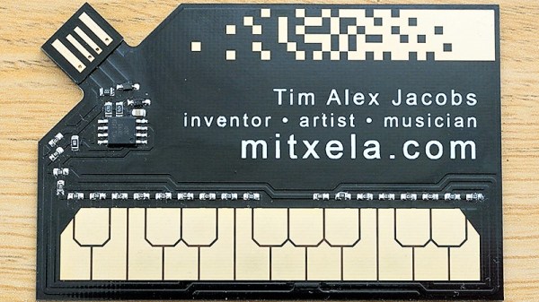
If you’re in the electronics business, PCB business cards seem like a natural fit. They may be impractical and expensive, but they can really set you apart from that boring paper card from Vistaprint crowd. But they need to make sense for what you do, so for a musician and MIDI pro, this MIDI-controller stylophone business card is a real eye- and ear-catcher.

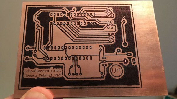
This business card is an idea that [Mitxela] has been kicking around for a while, and he even built a prototype a couple of years ago. The homebrew card, made using the spray paint, laser etching, and ferric chloride method, worked well enough as a proof of concept, but it was a little rough around the edges and needed the professional touch of a PCB fabricator. We’ve got to say that the finished cards are pretty darn sexy, with the black resist contrasting nicely against the gold-immersion pads. He selected a 1-mm thick board and made the USB connector as a separate small board; snapped off of the main board and reflowed back on, it builds up the edge connector to the proper thickness. The parts count is low — just an ATtiny85 and a resistor ladder to encode each key, with a simple jumper used as the stylus. The device itself is just a MIDI controller and makes no music on its own, but we still think this is a pretty creative way to hang out a shingle.

[Mitxela] has quite a few interesting builds, and is no stranger to our pages. Check out his recent servo-plucked MIDI music box, or these amazing miniature LED earrings.

Continue reading “Stylish Business Card With A Stylophone Built In”

A Brushless Motor On A PCB, Made From PCB

At Hackaday, we really appreciate it when new projects build on projects we’ve featured in the past. It’s great to be able to track back and see what inspires people to pick up someone else’s work and bring it to the next level or take it down a totally new path.

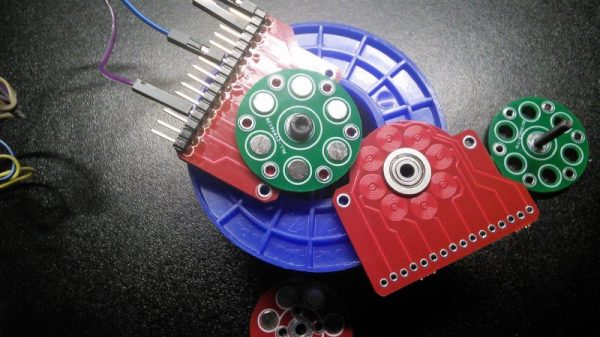
This PCB brushless motor is a great example of the soft collaboration that makes the Hackaday community so powerful. [bobricius] says he was inspired by this tiny PCB BLDC when he came up with his design. His write-up is still sparse at this point, but it looks like his motor is going to be used to drive a small robot. As with his inspiration, this motor has the stator coils etched right into the base PCB. But there are some significant improvements, like increasing the stator coil count from six to eight, as well as increasing the overall size of the motor. [bobricius] has also done away with the 3D-printed rotor of the original, opting to fabricate his rotor from stacked PCBs with cutouts for 5-mm neodymium magnets. We like the idea of using the same material throughout the motor, and it also raises the potential for stacking a second stator on the other side of the rotor, which might help mechanically and electrically. Even still, the prototype seems to hold its own in the video below.

This is [bobricius]’ second entry in the 2018 Hackaday Prize so far, after his not-a-Nixie tube display. Have you entered anything yet? Get to it! Prizes, achievements, and glory await.

Continue reading “A Brushless Motor On A PCB, Made From PCB”

Making Fancy Dice PCBs At Home

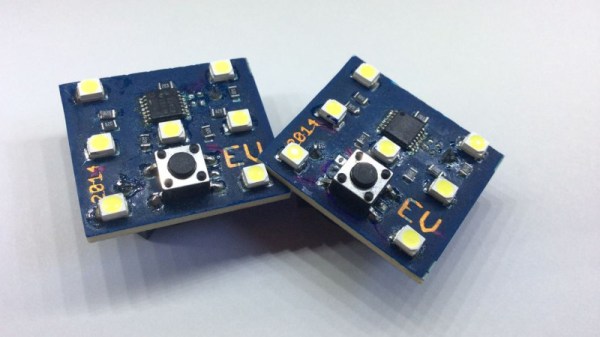
These days, it’s easy to get high-quality custom PCBs made and shipped to your door for under $50. It’s something that was unfathomable only a decade ago, but now it’s commonplace. However, it doesn’t mean that the techniques of home PCB production are now completely obsolete. Maybe you live somewhere a little off the beaten track (Australia, even!) and need to iterate quickly on a project, or perhaps you’d like to tinker with the chemical processes involved. For your learning pleasure, [Emiliano] decided to share some tips on making SMD-ready PCBs with the TinyDice project.

The actual project is to create a small electronic dice, and [Emiliano] touches on the various necessary considerations such as how to decrease power consumption, and how to source good quality, organic random numbers from your local microcontroller. Though its far from an exhaustive discussion on either topic, it shows an understanding of the deeper factors at play here.

However, the real meat of the write-up is the PCB production process. The guide goes through several stages of etching to not only prepare the PCB but also to add solder mask and produce a solder paste stencil as well using an aluminum can. This gives the boards that colored finish we’re all used to and lets the boards be reflowed for easy SMD assembly.

It’s a tidy guide as to how to approach producing your own boards to be used with SMD components, and it’s complete with clear photos and instructions throughout. If you want to take your designs up another notch, why not consider putting your components inside the circuit board?

The Fine Art Of Acid Etching Brass

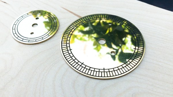
If you were building a recreation of the James Watt micrometer, where would you start? If you’re [rasp], the answer would be: “Spend a year trying to find the best way to make etched brass discs.” Luckily for us, he’s ready to share that information with the rest of the world. While it’s rather unlikely anyone else is working on this specific project, the methods he details for getting museum-quality results on brass are absolutely fascinating.

The process starts with sanding down the bare brass and applying a layer of clear packing tape to the metal. [rasp] then covers the piece with LaserTape, which is a special tape designed to make laser-cut masks for sandblasting. But the masking principle works just as well for painting or chemical etching.

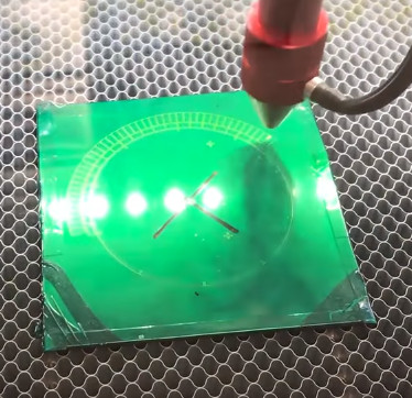
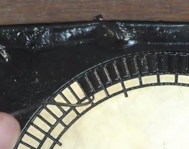
With the LaserTape in place, the piece is then put into the laser and the mask is cut out. Once cut, there’s the tedious task of peeling off all the cut pieces of tape, which [rasp] does with a dental pick. Once the pieces are pulled off, the brass is ready for its acid bath.

Anyone who’s etched their own PCB with ferric chloride will recognize these next steps. The piece is put into the acid bath and agitated every 10 minutes or so. It’s interesting to note that [rasp] places the piece in the bath upside-down, using little 3D printed “feet” to suspend the brass sheet off the bottom of the container. This allows the debris from the etching process to fall down and away from the piece. After about an hour out in the sun, the piece is pulled out of the bath and carefully washed off.

Once clean off, the piece is sprayed with black spray paint to darken up the etched areas. The moment of truth comes when the paint has dried and the layers of tape are carefully peeled back to reveal the etching. [rasp] then wet sands the piece with 1000 and 2000 grit paper, and a final pass with polishing compound brighten up the surface to a mirror-like shine. It’s quite a bit of manual labor, but the end result really is spectacular.

In the video after the break, [rasp] breaks down the entire process, including the additional machine work required to turn these brass plates into functional components of the final machine. As an added bonus, he even includes a lot of his failed attempts in an effort to keep others from making the same mistakes. Something we love to see here at Hackaday.

The process used here is similar to the snazzy brass name plates we showed earlier in the year, and has even been done without a laser using photoresist.

[via /r/DIY]

Continue reading “The Fine Art Of Acid Etching Brass”

Three Ways To Etch Snazzy Brass Nameplates

It’s the little touches that make a project, and a nice nameplate can really tie a retro build together. Such badges are easy enough to make with a CNC machine, but if you don’t have access to machine tools you can put chemistry to work for you with these acid-etched brass nameplates.

The etching method that [Switch and Lever] uses to get down to brass plaques will be intimately familiar to anyone who has etched a PCB before. Ferric chloride works as well on brass as it does on copper, and [Switch and Lever] does a good job explaining the chemistry of the etching process and offers some tips on making up etching solution from powdered ferric chloride. But the meat of the video below is the head-to-head test of three different masking methods.

The first method uses a laser printer and glossy paper ripped from a magazine to create a mask. The toner is transferred to the brass using an office laminator, and the paper removed with gentle rubbing before etching. For the other two candidates he uses a laser engraver to remove a mask of plain black spray paint in one case, or to convert special laser marking paint to a mask in the other.

We won’t spoil the surprise as to which gave the best results, but we think you’ll be pleased with how easy making classy nameplates can be. You can also use electrolytic methods for a deeper etch, but we think acid etching is a little more approachable for occasional use.

Continue reading “Three Ways To Etch Snazzy Brass Nameplates”

LED Fabrication From Wafer To Light

Building a circuit to blink an LED is the hardware world’s version of the venerable “Hello, world!” program — it teaches you the basics in a friendly, approachable way. And the blinky light project remains a valuable teaching tool right up through the hardware wizard level, provided you build your own LEDs first.

For [emach1ne], the DIY LED was part of a Master’s degree course and began with a slice of epitaxial wafer that goes through cleaning, annealing, and acid etching steps in preparation for photolithography. While gingerly handling some expensive masks, [emach1ne] got to use some really cool tools and processes — mask aligners, plasma etchers, and electron beam vapor deposition. [emach1ne] details every step that led to a nursery of baby LEDs on the wafer, each of which was tested. Working arrays were cut from the wafer and mounted in a lead frame, bonded with gold wires, and fiat lux.

The whole thing must have been a great experience in modern fab methods, and [emach1ne] should feel lucky to have access to tools like these. But if you think you can’t build your own semiconductor fab, we beg to differ.

[via r/engineering]

Entry-Level 3D Printer Becomes Budget PCB Machine

A funny thing happened on [Marco Rep]’s way to upgrading his 3D printer. Instead of ending up with a heated bed, his $300 3D printer can now etch 0.2-mm PCB traces. And the results are pretty impressive, all the more so since so little effort and expense were involved.

The printer in question is a Cetus3D, one of the newer generation of affordable machines. The printer has nice linear bearings but not a lot of other amenities, hence [Marco]’s desire to add a heated bed. But hiding beneath the covers was a suspicious transistor wired to a spare connector on the print head; a little sleuthing and a call to the factory revealed that the pin is intended for accessory use and can be controlled from G-code. With a few mods to the cheap UV laser module [Marco] had on hand, a printed holder for the laser, and a somewhat manual software toolchain, PCBs with 0.2-mm traces were soon being etched. The video below shows that the printer isn’t perfect for the job; despite the smooth linear bearings, the low mass of the printer results in vibration that shows up as wavy traces. But the results are more than acceptable, especially for $330.

This isn’t [Marco]’s first budget laser-etching rodeo. He recently tried the same thing using a cheap CNC laser engraver with similar results. That was a $200 dedicated engraver, this is a $300 3D printer with a $30 laser. It seems hard to lose at prices like these.

Continue reading “Entry-Level 3D Printer Becomes Budget PCB Machine”