Generative Design Algorithms Prepare For Space

NASA is famously risk-averse, taking cautious approaches because billions of taxpayer dollars are at stake and each failure receives far more political attention than their many successes. So while moving the final frontier outward requires adopting new ideas, those ideas must first prove themselves through a lengthy process of risk-reduction. Autodesk’s research into generative design algorithms has just taken a significant step on this long journey with a planetary lander concept.

It was built jointly with a research division of NASA’s Jet Propulsion Laboratory, the birthplace of many successful interplanetary space probes. This project got a foot in the door by promising 30% weight savings over conventional design techniques. Large reduction in launch mass is always a good way to get a space engineer’s attention! Mimicking mother nature’s evolutionary process, these algorithms output very organic looking shapes. This is a relatively new approach to design optimization under exploration by multiple engineering software vendors. Not just Autodesk’s “Generative Design” but also “Topology Optimization” in SolidWorks, plus others. Though these shapes appear ideally suited to 3D printing, Autodesk also had to prove their algorithm could work with more traditional fabrication techniques like 5-axis CNC mills.

This is leading-edge research technology though some less specialized, customer-ready versions are starting to trickle out of research labs. Starting with an exclusive circle: People with right tiers of SolidWorks license, the paid (not free) tier of Autodesk Fusion 360, etc. We’ve looked at another recent project with nontraditional organic shapes, and we’ve looked at generative designs used for their form as well as their function. This category of CAD tools hold a lot of promise, and we’re optimistic they’ll soon become widely accessible so we can all put them to good use in our earthbound projects.

Possibly even before they fly to another planet.

[via Engadget]

Scratch Built Toe Clamps Keep Your Work In Place

[Kevin] owns a benchtop CNC mill that has proven itself to be a capable tool, but after becoming familiar with some of its shortcomings, he has made a few modifications. In order to more efficiently hold and access workpieces on his custom fixturing table, he designed and made his own toe clamps and they look beautiful.

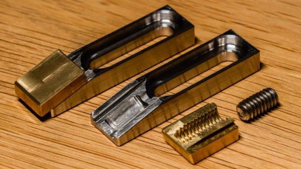
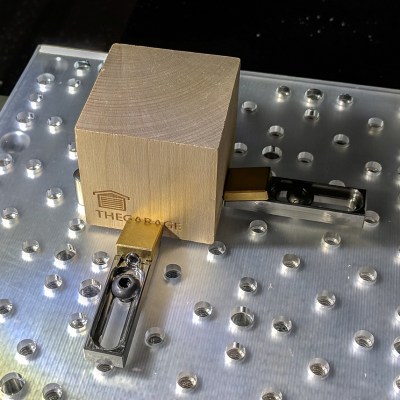
The usual way to secure a piece of stock to a fixturing table is to use top-down clamps, which hold the workpiece from the top and screw down into the table. However, this method limits how much of the stock can be accessed by the cutting tool, because the clamps are in the way. The most common way around this is to mount a vise to the table and clamp the workpiece in that. This leaves the top surface completely accessible. Unfortunately, [Kevin]’s benchtop Roland MDX-450 has a limited work area and he simply couldn’t spare the room. His solution was toe clamps, which screw down to the table and have little tabs that move inwards and downward. The tabs do the work of clamping and securing a piece of stock while maintaining a very low profile themselves.

The clamp bases are machined from stainless steel and the heads are brass, and the interface between the two is a set screw. Inserting a hex wrench and turning the screw moves the head forward or back, allowing a workpiece to be clamped from the sides with minimal interference. His design was done in Fusion 360 and is shared online.

Another option for when simple clamps won’t do the job is a trick from [NYC CNC], which is to use an unexpected harmony of blue painter’s tape and superglue which yields great results in the right circumstances.

Make 3D-Modeling Child’s Play With A Can Of Play-Doh

You need to replicate a small part on a 3-D printer, so you start getting your tools together. Calipers, rulers, and a sketch pad at a minimum, and if you’re extra fancy, maybe you pull out a 3D-scanner to make the job really easy. But would you raid your kid’s stash of Play-Doh too?

You might, if you want to follow [Vladimir Mariano]’s lead and use Play-Doh for accurately modeling surface features in the part to be replicated. Play-Doh is a modeling compound that kids and obsolete kids alike love to play with, especially a nice fresh can before it gets all dried out or mixed in with other colors or gets dog hair stuck in it.

For [Vladimir], the soft, smooth stuff was the perfect solution to the problem of measuring the spacing of small divots in the surface of a cylinder that he was asked to replicate. Rather than measuring the features directly on the curved surface, he simply rolled it across a flattened wad of Play-Doh. The goop picked up the impressions on the divots, which were then easy to measure and transfer to Fusion 360. The video below shows the Play-Doh trick up front, but stay tuned through the whole thing to get some great tips on using the sheet metal tool to wrap and unwrap cylinders, as well as learning how to import images and recalibrate them in Fusion 360.

Run into a modeling problem that Play-Doh can’t solve? Relax, we’ve got a rundown on the basics for you.

Continue reading “Make 3D-Modeling Child’s Play With A Can Of Play-Doh”

Printed Motorcycle Choke Lever Goes The Distance

We all dread the day that our favorite piece of hardware becomes so old that spare parts are no longer available for it, something about facing that mechanical mortality sends a little shiver up the hacker’s spine. But on the other hand, the day you can’t get replacement hardware is also the same day you have a valid excuse to make your own parts.

3D rendering above the 2D scan

That’s the situation [Jonathan] found himself in when the choke lever for his Suzuki motorcycle broke. New parts aren’t made for his bike anymore, which gave him the opportunity to fire up Fusion 360 and see if he couldn’t design a replacement using a 2D scan of what was left of the original part.

[Jonathan] put the original part on his flatbed scanner as well one of his credit cards to use for a reference point to scale the image when he imported it into Fusion 360. Using a 2D scanner to get a jump-start on your 3D model is a neat trick when working on replacement parts, and one we don’t see as much as you might think. A proper 3D scanner is cool and all, but certainly not required when replicating hardware like this.

The choke lever is a rather complex shape, one of those geometries that doesn’t really have a good printing orientation because there are overhangs all over the place. That combined with the fact that [Jonathan] printed at .3mm layer height for speed gives the final part an admittedly rough look, but it works. The part was supposed to be a prototype before he reprinted it at higher resolution and potentially with a stronger material like PETG, but after two years the prototype is still installed and working fine. This isn’t the first time we’ve seen a “temporary” 3D printed part become a long-term solution.


This is an entry in Hackaday’s

Repairs You Can Print contest

The twenty best projects will receive $100 in Tindie credit, and for the best projects by a Student or Organization, we’ve got two brand-new Prusa i3 MK3 printers. With a printer like that, you’ll be breaking stuff around the house just to have an excuse to make replacement parts.


Celebrating The Olympics With Flaming Windmills

Like many of us, [Gustav Evertsson] was looking for an excuse to set stuff on fire and spin it around really fast to see what would happen. Luckily for him (and us) the Winter Olympics have started, which ended up being the perfect guise for this particular experiment. With some motors from eBay and some flaming steel wool, he created a particularly terrifying version of the Olympic’s iconic linked rings logo. Even if you won’t be tuning in for the commercials Winter Games, you should at least set aside 6 minutes to watch this build video.

The beginning of the build starts with some mounting brackets getting designed in Fusion 360, and you would be forgiven if you thought some 3D printed parts were coming up next. But [Gustav] actually loads the design up on a Carbide 3D CNC and cuts them out of wood.

A metal hub is attached to each bracket, and then the two pieces are screwed onto a length of thin wood. This assembly is then mounted up to the spindle of a geared motor rated for 300 RPM. The end result looks like a large flat airplane propeller. Five of these “propellers” are created, one for each ring of the Olympic’s logo.

Once the sun sets, [Gustav] takes his collection of spinners outside and lines them up like windmills. At the end of each arm is a small ball of fine-grade steel wool, which will emit sparks for a few seconds when lighted. All you’ve got to do is get the 10 pieces of steel wool alight at the same time, spin up the motors, and let persistence of vision do the rest. If you can manage the timing, you’ll be treated with a spinning and sparking version of the Olympic rings that wouldn’t look out of place in a new Mad Max movie.

Generally speaking, we don’t see much overlap between the hacker community and the Olympics. You’d have to go all the way back to 2012 to find another project celebrating this particular display of athleticism. We would strongly caution you not to combine both of these Olympic hacks at the same time, incidentally.

Continue reading “Celebrating The Olympics With Flaming Windmills”

Printed Adapter Teaches An Old Ninja New Tricks

Do you like change for the sake of change? Are you incapable of leaving something in a known and working state, and would rather fiddle endlessly with it? Are you unconcerned about introducing arbitrary compatibility issues into your seemingly straight-forward product line? If you answered “Yes” to any of those questions, have we got the job for you! You can become a product engineer, and spend your days confounding customers who labor under the unrealistic expectation that a product they purchased in the past would still work with seemingly identical accessories offered by the same company a few years down the line. If interested please report to the recruitment office, located in the darkest depths of Hell.

A 2D representation of the adapter in Fusion 360

Until the world is rid of arbitrary limitations in consumer hardware, we’ll keep chronicling the exploits of brave warriors like [Alex Whittemore], who take such matters into their own hands. When he realized that the blades for his newer model Ninja food processor didn’t work on the older motor simply because the spline was a different size, he set out to design and print an adapter to re-unify the Ninja product line.

[Alex] tried taking a picture of the spline and importing that into Fusion 360, but in the end found it was more trouble than it was worth. As is the case with many printed part success stories, he ended up spending some intimate time with a pair of calipers to get the design where he wanted it. Once broken down into its core geometric components (a group of cylinders interconnected with arches), it didn’t take as long as he feared. In the end the adapter may come out a bit tighter than necessary depending on the printer, but that’s nothing a few swift whacks with a rubber mallet can’t fix.

This project is a perfect example of a hack that would be much harder (but not impossible) without having access to a 3D printer. While you could create this spline adapter by other means, we certainly wouldn’t want to. Especially if you’re trying to make more than one of them. Small runs of highly-specialized objects is where 3D printing really shines.


This is an entry in Hackaday’s

Repairs You Can Print contest

The twenty best projects will receive $100 in Tindie credit, and for the best projects by a Student or Organization, we’ve got two brand-new Prusa i3 MK3 printers. With a printer like that, you’ll be breaking stuff around the house just to have an excuse to make replacement parts.


Repairing A Wounded Mantis

While it’s true that we didn’t specifically say making Hackaday staff exceedingly jealous of your good fortune would deduct points from your entry into our ongoing “Repairs You Can Print Contest”, we feel like [Sam Perry] really should have known better. During a recent dumpster dive he found an older, slightly damaged, but still ridiculously awesome Mantis stereo inspection microscope. Seriously, who’s throwing stuff like this away?

Rendered replacement mount in Fusion 360

Apparently, the microscope itself worked fine, and beyond some scratches and dings that accumulated over the years, the only serious issue was a completely shattered mount. Luckily he still had the pieces and could get a pretty good idea of what it was supposed to look like. After what we imagine was not an insignificant amount of time in Fusion 360, he was able to model and then print a replacement.

The replacement part was printed on a Tronxy P802M in PLA. Even at 0.3mm layer height, it still took over 10 hours to print such a large and complex component. A few standard nuts and bolts later, and he had a drop-in replacement for the original mount.

Whether it’s due to how big and heavy the Mantis is, or a slight miscalculation in his model, [Sam] does mention that the scope doesn’t sit perfectly level; he estimates it’s off by about 5 degrees.

We’re somewhat suspicious that mentioning an error of only 5 degrees is a stealth-brag on the same level as telling everyone you found a Mantis in the trash. But if [Sam] gives us the GPS coordinates of the dumpster in which people are throwing away high-end lab equipment, all will be forgiven.

There’s still plenty of time to get your entry into the “Repairs You Can Print” contest! The top twenty projects will receive $100 in Tindie store credit, and the top entries in the Student and Organization categories will each receive a Prusa i3 MK3 with the Quad Material upgrade kit: arguably one of the best 3D printers currently on the market. If you were considering going back to school, or finally leaving your basement and joining a hackerspace, now would definitely be the time.