A Game Of Snake On A LEGO Mechanical Computer

Really, [OzzieGerff] had us at “LEGO.” But then he took it to another place entirely and built a completely mechanical, nearly 100% LEGO version of Snake. And it’s just as cool as it sounds.

Mind you, it’s a little hard to grok how this whole contraption works, which has been in the works for a while, but we’ll try to summarize as best we can. The most important aspect of this build is that there are no electronics at all — everything is done with mechanical linkages, with some Technics pneumatic components and a couple of electric motors to provide the oomph. The three main components are the input section, which consists of a two-axis joystick, a tail buffer, which keeps track of the length of the snake’s tail as gameplay progresses, and the largest component, the 16×16 display.

The joystick translates user inputs into pneumatic signals which pass through a mechanical filtering unit that prevents the head of the snake from doubling back on itself. The filtered inputs then pass into the screen reader, a complex device that probes the status of a given pixel on the display and determines the status of the snake’s head. If it touches a snake pixel, the game’s over. Hitting a blank pixel moves the head of the snake by one and takes one pixel off the end, while a food pixel extends the snake’s length.

Keeping track of the length of the snake is the job of the buffer, which uses Technics tank tracks and levers. Setting a one is done by flipping the lever to one side as it passes under the write head; a read head further down the track senses which way the lever is flipped and translates it into a pneumatic signal. The buffer has four channels, one for each possible direction the snake’s head could be moving. The signals drive a screen writer, which moves a pyramidal follower across a series of push-rods that flip the corresponding pixel on the display to show the proper icon. Simplicity itself? No, but the video below will make things a lot clearer.

It doesn’t look like [Ozzie] is quite done with this game, as he doesn’t show any actual gameplay yet. We’d love to see and hear that — we suspect it’ll make quite a racket. We’ll be keeping an eye out for this one, but while we wait, check out this rope braiding machine or watch Lego break steel.

Continue reading “A Game Of Snake On A LEGO Mechanical Computer”

Electronic Etch-A-Sketch, No Microcontroller Required

In a lot of ways, Etch-A-Sketch is the perfect toy; simple, easy to use, creative, endlessly engaging, and as a bonus, it’s completely mechanical. We find that last attribute to be a big part of its charm, but that’s not to say an electronic version of the classic toy can’t be pretty cool, especially when it’s done without the aid of a microcontroller.

This is one of those “because I can” projects that we always find so interesting, and more so because it wasn’t entirely clear to [BigZaphod] that he had the skills to pull it off. While his initial design centered around a bunch of 8×8 LED matrix displays and a 256×4-bit RAM chip, the rest of it was a lot of hand-waving. After a few experiments with addressing the LEDs, [Zaphod] started filling in the blanks with a refresh circuit using a 555 — naturally — and a pair of counters. Properly debounced encoders for the horizontal and vertical controls came next, along with more counters to track the cursor and a host of other circuits that ended up looking like a “one of each” selection from the 7400-series catalog.

While we do wish for a schematic on this one, it’s still a pretty enjoyable video, and the end product seems to work really well. The electronic version has a few features the original lacks, such as wrapping the cursor to the other side of the screen. We’d imagine that the buttons on the encoders could be put to work, too; perhaps a click could make it so you can move the cursor without leaving a trail behind. That might be a challenge to execute in logic, but then again, that was the point of the whole thing.

Still jonesing for that mechanical Etch-A-Sketch experience? Not a problem.

Continue reading “Electronic Etch-A-Sketch, No Microcontroller Required”

Keeping Track Of The Night Sky With Discrete Logic Chips

As hobbies go, stargazing has a pretty low barrier to entry. All you really need is a pair of Mark 1 eyeballs and maybe a little caffeine to help you stay up late enough. Astronomy, on the other hand, takes quite a bit more equipment, not least of which is a telescope and a way to get it pointed in the right direction at the right time, and to make up for the pesky fact that we’re on a moving, spinning ball of rock.

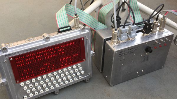
Yes, most of the equipment needed for real astronomy is commercially available, but [Mitsuru Yamada] decided to go his own way with this homebrew retro-style telescope motor controller. Dubbed MCT-6, the controller teams up with his dual-6502 PERSEUS-9 computer to keep his scope on target. There are a lot of literally moving parts to this build, including the equatorial mount which is made from machined aluminum and powered by a pair of off-the-shelf stepper-powered rotary stages for declination and right ascension. The controller that runs the motors is built completely from discrete 74HCxx logic chips that divide down a 7.0097-MHz crystal oscillator signal to drive the steppers precisely at one revolution per diurnal day. The pulse stream can also be sped up for rapid slewing, to aim the telescope at new targets using a hand controller.

As impressive as all this is, the real star (sorry) of the show here is the fit and finish. In typical [Yamada-san] fashion, the impeccably wire-wrapped mainboard fits in a robust die-cast aluminum case that fits the retro aesthetic of the whole project. The PERSEUS-9 is used mainly as a display and control terminal, running custom software to show where the telescope is pointed and calculate the coordinates of various heavenly bodies. As a bonus, the 40×7 alphanumeric red LED display should be easy on dark-adapted eyes.

Hats off to [Mitsuru Yamada] on another fabulous build. If you haven’t had enough of his build style yet, be sure to check out his PERSEUS-8 or even his foray into the analog world.

Continue reading “Keeping Track Of The Night Sky With Discrete Logic Chips”

The Other Kind Of Static Hazard To Your Logic Circuits

We’ve all heard of the dangers of static electricity when dealing with electronics, and we all take the proper precautions when working with static-sensitive components — don’t we? But as much as we fear punching an expensive hole in a chip with an errant spark, electrostatic discharge damage isn’t the only kind of static hazard your digital designs can face.

To be fair, the static hazard demonstrated by [Shane Oberloier] in the video below isn’t really an electrostatic problem. “Static” in this case refers to when a change to an input of a logic circuit gives an unexpected output until the circuit stabilizes. The circuit shown is pretty simple, with three inputs going into a combination of AND and NOT gates before going into an OR gate. The static hazard manifests as a glitch in the output when the middle input line’s logical state is toggled; according to the circuit’s truth table, the output shouldn’t change under these conditions, but the oscilloscope clearly captures a high-low-high blip. [Dr. Shane]’s explanation of why this happens makes perfect sense: the inverter on that input line has a brief but non-zero propagation time, putting the whole circuit in an ambiguous state before finally settling down to the correct output value.

So how do you fix something like this? This gets into the Boolean weeds a bit, and we won’t pretend to fully understand it, but at least for this case, [Dr. Shane] was able to add a single AND gate to sum the two other inputs and pipe the output into another input of the OR gate. That has the effect of canceling out the race condition caused by the inverter, but at the expense of a more complicated circuit, of course.

We found this to be a fascinating and informative discussion of a potential pitfall in logic design. But, if you still want to see some MOSFETs executed with static electricity, who are we to object?

Continue reading “The Other Kind Of Static Hazard To Your Logic Circuits”

Partial Relay-Based Calculator Puts The Click Where It Counts

It looks like [Michal Zalewski] is raising the next generation the right way. First, his eldest son asks for help building a one-bit computer from discrete transistors. Not to be left behind, his little brother then asked for help with an even more retro project, which resulted in this partially relay-based calculator. Maybe there is some hope for the future.

Now, purists will no doubt notice the ATmega64 microcontroller sitting in the middle of the main PCB on this project and cry “Foul!” But perfect is the enemy of done, and as [Michal] explains, at $6 a pop for the Omron relays he and his son chose, there’s only so far you can go with relay logic before you’re taking out a second mortgage. So the relays are limited to the ALU of the calculator, along with the drivers for the six seven-segment LED displays. The microcontroller is just there for housekeeping functions like scanning the keyboard and decoding digits. All the actual calculations are in the relay logic, not silicon. And we’d be remiss not to praise his son’s stylistic choices for this design — that it uses relays with clear covers, and that it has single-sided PCBs with curvy, hand-drawn traces traces that look hand-drawn on old-school yellow substrate. [Michal]’s heart must swell with pride to have fathered someone with such exquisite taste.

For his part, [Mikal] did some really good documentation for this build, including excellent descriptions of Boolean math with half- and full-adders and how relays are used to create the basic logic gates that comprise them. The calculator itself is still a work in progress, with microcontroller code still in development, but it’s working enough that you can enjoy the display driver’s clickiness in the video below. If that doesn’t do it for you, we’ve got other relay calculators to scratch that click itch. Continue reading “Partial Relay-Based Calculator Puts The Click Where It Counts”

Patching Together Logic Gates

The digital world offers many advantages over its analog relatives, the use of boolean logic among them. Some of the functions, like NOT, OR, and AND are fairly straightforward and line up nicely with their linguistic counterparts. Others are more elusive, like XOR and NAND. For those just getting their start in digital logic, this teaching tool allows different logic gates to be wired together with patch cables.

While [David] first thought to use 74-series logic circuits directly, a much more versatile solution was to use configurable custom logic — a feature found in AVR DA-series microcontrollers that allows for the creation of custom logic circuits without the need for external hardware or complex programming. He went with an ATmega4809 which is capable of supporting twelve gates which are depicted graphically on the board, where the patch cables can be connected between inputs and outputs from a set of switches on the left to another set of LEDs on the right. The microcontroller continually polls for connections, applies the correct logic via a lookup table, and lights the appropriate LED.

Even with only twelve gates, the amount of real-world analogs that can be created with this teaching tool are numerous and varied, from simple things like displaying traffic light patterns in the correct order to implementing a binary adder. It’s an excellent way to get started in digital logic or understanding gates, and much simpler than dealing with 74-series chips on a breadboard like many of us might have done, but those logic chips can be powerful tools to have on hand even in the modern world of microcontrollers.

GLASNOST Is A Computer That Makes Transparency A Priority

We live in a world where most of us take the transistor for granted. Within arm’s length of most people reading this, there are likely over ten billion of them sending electrons in every direction. But the transistor was not the first technology to come around to make the computer a possibility, but if you go to the lengths of building something with an alternative, like this vacuum tube computer, you may appreciate them just a tiny bit more.

This vacuum tube computer is called GLASNOST, which according to its creator [Paul] means “glass, no semiconductors” with the idea that the working parts of the computer (besides the passive components) are transparent glass tubes, unlike their opaque silicon-based alternatives. It boasts a graphical display on an oscilloscope, 4096 words of memory, and a custom four-bit architecture based only on NOT, NOR, and OR gates which are simpler to create with the bulky tubes.

The project is still a work in progress but already [Paul] has the core memory figured out and the computer modeled in a logic simulator. The next steps are currently being worked through which includes getting the logic gates to function in the real world. We eagerly await the next steps of this novel computer and, if you want to see one that was built recently and not in the distant past of the 1950s, take a look at the Electron Tube New Automatic Computer that was completed just a few years ago.