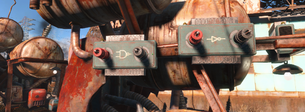

Fallout 4, the latest tale of post-apocalyptic tale of wasteland wanderers, got its latest DLC yesterday. This add-on, Contraptions Workshop, adds new objects and parts to Fallout 4‘s settlement-building workshop mechanic. This add-on brings more building pieces, elevators, and most importantly logic gates to Commonwealth settlements.
The Fallout logic gates are used in conjunction with electric generators, lights, and automated sentries used to build settlements. Although a simple NAND would do, there are several types of logic gates including AND, OR, XOR, NOT, NAND, NOR, and XNOR.
The in-game explanation for these gates is very, very weird. AND, OR, and XOR “transmit power or not depending on the combination of power to their inputs”. NOT, NAND, NOR, and XNOR are apparently different, “only transmitting power if their inputs are connected directly to the output of other logic gates”. The reason for this arbitrary distinction between different sets of gates is currently unknown except to a few programmers and project leaders at Bethesda. It should be noted {AND, OR, XOR} is not functionally complete.
With implementations of logic gates in video games comes some very interesting if useless applications. Already Fallout 4 has light boxes, allowing for huge animated billboards. Fallout speakers, the wasteland’s equivalent of Minecraft’s note block, can be used to play simple melodies. You can do anything with a NAND, so we would expect automated, sequenced versions of animated billboards and monophonic synthesizers to appear in short order.
Functional completeness can add a lot to a game. Since Minecraft added redstone logic to the game, we’ve seen some very, very impressive block-based builds. The Minecraft CPU generally regarded as being the first, most complete CPU took about three months to design and build. This build didn’t use later additions to the redstone toolbox like repeaters, pistons, and the now-cheaty command blocks.







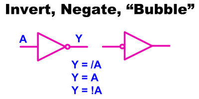 The most simple piece of logic is inversion; making a high change to low or a low change to high. Shown are a couple of ways to write an inversion including the ubiquitous “bubble” that we can apply almost anywhere to imply an inversion or a “True Low”. If it was a one it is now a zero, where it was a low it is now a high, and where it was true it is now untrue.
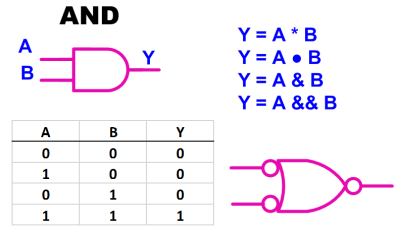 Moving on to the AND gate we see a simple truth table, also known as a Boolean Table, where it describes the function of “A AND B”. This is also our first opportunity to see the application of an alternate symbol. In this case a “low OR a low yields a low”
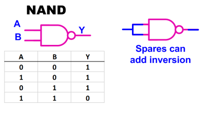 Most if not all of the standard logic blocks come in an inverted form also such as the NAND gate shown here. The ability to invert logic functions is so useful in real life that I probably used at least three times the number of NAND gates as regular AND gates when doing medium or larger system design. The useful inversion can occur as spares or in line with the logic.