As hobbies go, stargazing has a pretty low barrier to entry. All you really need is a pair of Mark 1 eyeballs and maybe a little caffeine to help you stay up late enough. Astronomy, on the other hand, takes quite a bit more equipment, not least of which is a telescope and a way to get it pointed in the right direction at the right time, and to make up for the pesky fact that we’re on a moving, spinning ball of rock.
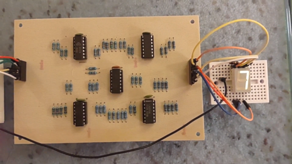
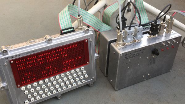
Yes, most of the equipment needed for real astronomy is commercially available, but [Mitsuru Yamada] decided to go his own way with this homebrew retro-style telescope motor controller. Dubbed MCT-6, the controller teams up with his dual-6502 PERSEUS-9 computer to keep his scope on target. There are a lot of literally moving parts to this build, including the equatorial mount which is made from machined aluminum and powered by a pair of off-the-shelf stepper-powered rotary stages for declination and right ascension. The controller that runs the motors is built completely from discrete 74HCxx logic chips that divide down a 7.0097-MHz crystal oscillator signal to drive the steppers precisely at one revolution per diurnal day. The pulse stream can also be sped up for rapid slewing, to aim the telescope at new targets using a hand controller.
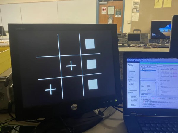
As impressive as all this is, the real star (sorry) of the show here is the fit and finish. In typical [Yamada-san] fashion, the impeccably wire-wrapped mainboard fits in a robust die-cast aluminum case that fits the retro aesthetic of the whole project. The PERSEUS-9 is used mainly as a display and control terminal, running custom software to show where the telescope is pointed and calculate the coordinates of various heavenly bodies. As a bonus, the 40×7 alphanumeric red LED display should be easy on dark-adapted eyes.
Hats off to [Mitsuru Yamada] on another fabulous build. If you haven’t had enough of his build style yet, be sure to check out his PERSEUS-8 or even his foray into the analog world.
Continue reading “Keeping Track Of The Night Sky With Discrete Logic Chips”