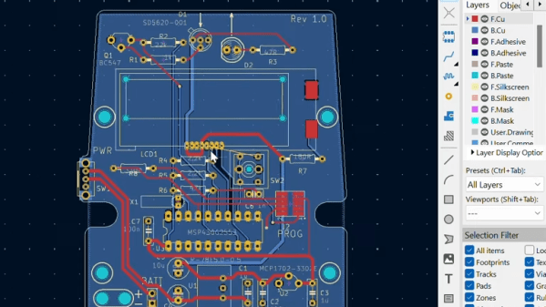
[Sebastian] probably didn’t think he was wading into controversial waters when he posted on his experimental method for etching PCBs (in German). It’s not like etching with hydrochloric acid and peroxide is anything new, really; it was just something new to him. But is it even possible these days to post something and not find out just how wrong you are about it?
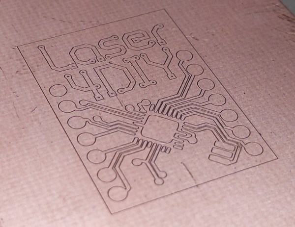
Sadly, no, or at least so it appears from a scan of [Sebastian]’s tweet on the subject (Nitter). There are a bunch of ways to etch copper off boards, including the messy old standby etchant ferric chloride, or even [Sebastian]’s preferred sodium persulfate method. Being out of that etchant, he decided to give the acid-peroxide method a go and was much pleased by the results. The traces were nice and sharp, the total etching time was low, and the etchant seemed pretty gentle when it accidentally got on his skin. Sounds like a win all around.
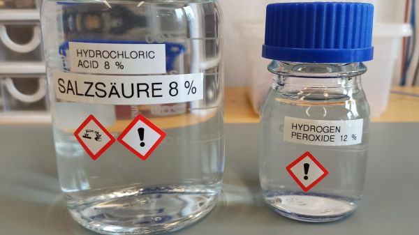
But Twitter wouldn’t stand for this chemical heresy, with comments suggesting that the etching process would release chlorine gas, or that ferric chloride is far safer and cleaner. It seems to us that most of the naysayers are somewhat overwrought in their criticism, especially since [Sebastian]’s method used very dilute solutions: a 30% hydrochloric acid solution added to water — like you oughta — to bring it down to 8%, and a 12% peroxide solution. Yes, that’s four times more concentrated than the drug store stuff, but it’s not likely to get you put on a terrorism watch list, as some wag suggested — a hair stylist watchlist, perhaps. And 8% HCl is about the same concentration as vinegar; true, HCl dissociates almost completely, which makes it a strong acid compared to acetic acid, but at that dilution it seems unlikely that World War I-levels of chlorine gas will be sweeping across your bench.
As with all things, one must employ caution and common sense. PPE is essential, good chemical hygiene is a must, and safe disposal of spent solutions is critical. But taking someone to task for using what he had on hand to etch a quick PCB seems foolish — we all have our ways, but that doesn’t mean everyone else is wrong if they don’t do the same.
Continue reading “Different Etching Strokes For Different PCBs, Folks”