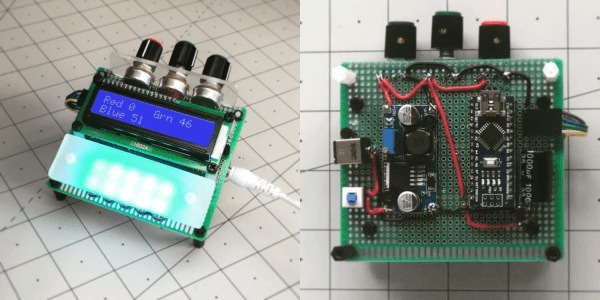
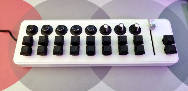
Axe Hacks: Spinning Knobs And Flipping Switches

From a guitar hacking point of view, the two major parts that are interesting to us are the pickups and the volume/tone control circuit that lets you adjust the sound while playing. Today, I’ll get into the latter part and take a close look at the components involved — potentiometers, switches, and a few other passive components — and show how they function, what alternative options we have, and how we can re-purpose them altogether.

In that sense, it’s time to heat up the soldering iron, get out the screwdriver, and take off that pick guard / open up that back cover and continue our quest for new electric guitar sounds. And if the thought of that sounds uncomfortable, skip the soldering iron and grab some alligator clips and a breadboard. It may not be the ideal environment, but it’ll work.

Continue reading “Axe Hacks: Spinning Knobs And Flipping Switches”

DIY Ribbon Controller For A DIY Synth

There’s kind of a special joy in making instruments, no matter how simple or complex they are. Even if it’s a straight-up noisemaker, that’s noise you can be proud of. And besides, noise plus rhythm equals music.

Whenever you’re ready to have some next-level fun, try making controllers for your DIY instruments. Synthesizers of all stripes are often controlled with various types of potentiometers. While it would definitely be an interesting exercise to make your own standard twist-style potentiometer, [lonesoulsurfer] shows that making a ribbon controller is relatively easy.

A ribbon controller is essentially a deconstructed potentiometer that uses your finger to actuate the wiper. Here the wiper is made from Velostat, a fun, low-cost conductive material that’s also pressure-sensitive. The rest of the ribbon controller is a sandwich of thin copper plates and non-conductive plastic mounted on a wood base.

But what’s a fun controller without a fun instrument to control? As a special bonus, [lonesoulsurfer] made a little square wave-squirting synth based on the 4046 hex inverter and included the schematic for it. Slide your finger past the break to check ’em both out.

Depending on what you have lying around, it may be easier to make analog instruments like this rubber band boinger or its country cousin, the wheelbarrow bass.

Continue reading “DIY Ribbon Controller For A DIY Synth”

RGB Kitchen Uses Pots To Stir Up Color

Anyone who has done anything with RGB LEDs knows that their ability to display pretty much any color is somehow both the best and worst thing about them. How do you get it right? How do you make your results repeatable? [Thomas] has the answer. He dug around in the ol’ parts cupboard, found a few pots, and got to work making this stay-home stew of a project — an on-demand RGB LED color mixer.

Three cleverly color-coded potentiometers and an Arduino let [Thomas] step through 0-255 to mix various values of red, blue, and green. The shade that gets made is displayed live on a set of 10 individual NeoPixels that are laid out under a frosty diffusing panel. Each of the RGB values are also shown on an 16×2 LCD.

This is one of those projects that hits a sweet spot of being simple, useful, and fun. It’s even nice-looking and compact. What more could you want from a project cobbled together from ingredients on hand? [Thomas] is even giving away the code recipe.

Once you dial in your ideal colors, why not make a gesture-controlled lamp?

Simon Says, But With Servos

How much easier would life be if you could just grab hold of whatever mechanism you wanted to manipulate, move it like you want, and then have it imitate your movements exactly? What if you could give a servo MIDI-like commands that tell it to move to a certain location for a specific duration? Wonder no more, because [peterbiglab] has big-brained the idea into fruition.

With just one wire, an Arduino, and some really neat code, [peter] can get this servo to do whatever he wants. First he tells the Arduino the desired duration in frames per second. Then he grabs the horn and moves it around however he wants — it can even handle different speeds. The servo records and then mimics the movements just as they were made.

The whole operation is way simpler than you might think. As [peterbiglab] demonstrates in the video after the break, the servo knows its position thanks to an internal potentiometer on the motor’s rotor. If you locate the pot output pin on the control board and run a wire from there into an Arduino, you can use that information to calibrate and control the servo’s position pretty easily. There are a ton of possibilities for this kind of control. What would you do with it? Let us know in the comments.

If you want to try this with a bunch of servos at once, might as well build yourself a little testing console.

Continue reading “Simon Says, But With Servos”

Upgrading A MIDI Controller With An FPGA

While the “M” in MIDI stands for “musical”, it’s possible to use this standard for other things as well. [s-ol] has been working on a VJ setup (mixing video instead of music) using various potentiometer-based hardware and MIDI to interface everything together. After becoming frustrated with drift in the potentiometers, he set out to outfit the entire rig with custom-built encoders.

[s-ol] designed the rotary-encoder based boards around an FPGA. It monitors the encoder for changes, controls eight RGB LEDs per knob, and even does capacitive touch sensing on the aluminum knob itself. The FPGA communicates via SPI with an Arduino master controller which communicates to a PC using a serial interface. This is [s-ol]’s first time diving into an FPGA project and it looks like he hit it out of the park!.

Even if you’re not mixing video or music, these encoders might be useful to any project where a standard analog potentiometer isn’t accurate or precise enough, or if you just need something that can dial into a specific value quickly. Potentiometers fall short in many different ways, but if you don’t want to replace them you might modify potentiometers to suit your purposes.

Continue reading “Upgrading A MIDI Controller With An FPGA”

Switching Over To SMPS For Efficiency

[Hesam Moshiri] has built a variable switch-mode power supply over on hackaday.io. When prototyping a new circuit, often the goal is to get a proof-of-concept working as soon as possible to iron out all of the bugs it might have. The power supply can easily be an afterthought, and for smaller projects we might just reach for an adjustable LM317 voltage regulator to dial in the correct voltage and then move on with the meat of the project. These linear regulators are incredibly inefficient though, so if you find yourself prototyping with one of these often enough, it might be worthwhile to switch to something better.

While it’s easy to simply buy a switch-mode power supply (SMPS) that has everything you need, and rated for 90% or higher efficiency at the same time, getting one with an adjustable output isn’t as easy. This one is based on the relatively popular LM2576-Adj chip which handles the switching frequency part of the circuit automatically. You will also need some large capacitors, an inductor (one of the disadvantages of an SMPS circuit) and a small potentiometer to use as the feedback control for the LM2576. This special pin allows the output voltage of the SMPS to be precisely controlled.

Granted, this project might not be breaking any new grounds, but if you’ve never given serious thought to your small breadboard circuit power supplies, it’s definitely worth looking into. An improvement from a linear regulator’s 30% efficiency to 90% efficiency from an SMPS will not only save you a ton of energy but also solve a lot of heat dissipation problems. If you don’t want to build a switch-mode supply 100% from scratch, though, it might also be possible to modify an existing one to suit your needs as well.

Better Simulators With Homemade Potentiometers

Perhaps you’ve played a flight simulator before, using something like a mouse and keyboard. That’s a fine experience, but like any other activity you can get a lot more out of it if you put a little more effort into the experience. Some will upgrade to a joystick for a modest improvement, and others will build incredible accurate cockpit replicas down to the smallest detail. The builders of these “pits” are always looking for ways of improving their setups, and it’s from this world that we find a method of building specialized, inexpensive hall-effect sensors.

A hall-effect sensor is a circuit that outputs a voltage based on the presence of an external magnetic field. These can be used to make compasses, but with a permanent magnet in close proximity can also be used to create a potentiometer-like device at lower cost and with higher precision than a similarly-priced pot. There was a method of building these in the simulator world using the housing of a Bic pen and some strong glue, but [LocNar] has improved on this method as well. He repurposed some bearings and some stock metal tubing in order to fabricate a professional-level sensor at a fraction of the cost.

This build is essentially a solution for anyone needing a potentiometer that’s easier to build, less expensive, has higher precision, and interacts with a digital input in a much more predictable (and programmable) way. Certainly this has applications in the simulator world, but will work for many other applications. If you’ve never thought about the intricacies (and shortcomings) of potentiometers, some other folks have taken a deep dive into that as well.

Thanks to [Keith O] for the tip!