A Solari Mechanical Digital Clock Hack With A Little Extra

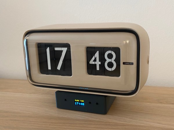
[Alfredo Cortellini] was perusing an antique shop in Bologna, and came across a nice example of a late 1950s timepiece, in the shape of a Solari Cifra 5 slave clock, but as the shop owner warned, it could never tell the time by itself. That sounded like a challenge, and the resulting hack is a nice, respectful tweak of the internals to bring it into the modern era. Since the clock requires a single pulse-per-minute in order to track time, the simplest track often followed is to open the back, set the correct time manually by poking the appropriate levers, and then let an external circuit take over clocking it. [Alfredo] wanted autonomy, and came up with a solution to make the thing fully adjust itself automatically.

Electronics-wise, initial prototyping was performed with a Nucleo 32 dev board and a pile of modules, before moving to a custom PCB designed in Altium Designer. An STM32G031 runs the show, with a few push buttons and a SSD1306 OLED display forming the UI.

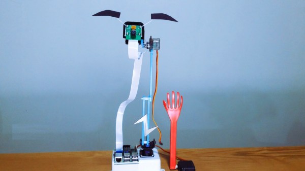
Using some strategically-placed magnets and hall effect sensors, the status of the internal mechanism could be determined. Minute advancements were effected by driving the clock’s 24V electromagnet with a DRV8871 motor driver IC, the power supply for which was generated from the USB supply via a TPS61041 boost converter. In order to synchronise the mechanism with the electronics, the unit could have been driven to advance a minute at a time, but since every hour would need sixty pulses, this could take a while given the limited speed at which that could be done reliably. The solution was to sneak in a crafty MG996R high-torque servo motor, which pushes on the hour-advancement lever, allowing the unit to be zeroed much faster. Sensing of the zero-hour position was done by monitoring the date-advance mechanism, that is not used in this model of clock. Once zeroed, the clock could then be advanced to the correct time and kept current. Firmware source, utililising FreeRTOS can be found on the project GItHub, with schematics and Fusion360 files on the Hackaday.IO project linked above.

If you were thinking you’ve seen these Solari soft-flap displays here before, you’d be quite correct, but if you’re not so much interested in marking the passage of time, but bending such devices to your other indication whims, we’ve got you covered also.

Continue reading “A Solari Mechanical Digital Clock Hack With A Little Extra”

Servo Larson scanner

No LEDs Required For This Servo-Controlled Larson Scanner

All things considered, it’s pretty easy to get one LED is a strip to light up sequentially, and have it bounce back and forth. Turning that simple animation into a real Larson scanner, with smooth transitions and controlled fade-out, is another thing entirely. And forgetting the LEDs altogether and making a servo-operated Larson scanner is — well, let’s just call it an interesting lesson in hardware abstraction.

The Larson scanner, named after famed TV producer Glen A. Larson for his penchant for incorporating it into shows like Battlestar Galactica and Knight Rider, is actually hard to execute in hardware thanks to the fading tail that follows the lead pixel as it dances back and forth across the display. [Eric Gunnerson] decided to make this and other animation effects easier to achieve with Fade, a custom framework for LED animations that runs on an ESP32.

LED animations are fine, but what about servos? Could Fade be modified to support them? This turned out to be a fairly easy mod thanks to Fade’s architecture and [Eric]’s existing support for non-addressable LEDs via PWM signals. And it was even possible to support more than the 16 PWM channels on an ESP32by adding a UDP connection that puts multiple ESP32s under the control of a central microcontroller.

The video below shows [Eric]’s demo of servo support, with an eight-channel electromechanical Larson scanner. Each “pixel” is a painted ping pong ball swinging back and forth on a hobby servo, and the whole thing sounds just about as awful as you’d expect it to. If you squint just right, the effect looks pretty convincing, but that’s hardly the point. The real story here is [Eric]’s thoughtful architecture, which made the mods easier than starting from scratch.

Continue reading “No LEDs Required For This Servo-Controlled Larson Scanner”

Forget Sudoku, Build Yourself A Minimalist Rubik’s Solver Robot

Some people like crossword puzzles, some are serious sudoku ninjas, but [Andrea Favero] likes to keep himself sharp, by learning coding and solving control problems, and that is something we can definitely relate to. When learning a new platform, it’s a very good idea to have a substantial project or goal in mind, and learn what is needed on the way there. [Andrea] chose to build an autonomous Rubik’s cube solver, and was kind enough to document exactly how how to do it, and we’re glad of it!

The result of the openCV processing chain

Working in python with OpenCV, [Andrea] uses the methodology by [Oussama Barkouki] to process each face image and convert it into a table of the colours of individual facelets. The basics of that, are first to convert the image to grayscale, then use a gaussian blur to denoise the image. Edges are identified using the canny algorithm, the result of which is then dilated and passed into a contour detector. The contours are sent into a cunning filter that identifies square contours, and those the wrong size are filtered off. What you’re left with are the outlines of the actual coloured facelets. Once you have a list of squares, these can be used to form image masks, and thence select the average colour from each square. The colour is then quantised and stored as a labelled colour from the standard Western Rubik’s cube colour scheme. Finally, once all face images are captured and facelets colours identified, the data are passed into a Rubik’s cube solving algorithm developed by [Hegbert Kociemba,] a guide to which is available on the speedsolving site. The result of the solving step is a sequence of descrambling moves, in the move notation developed by [David Singmaster]. Fascinating stuff, if you ask us! Continue reading “Forget Sudoku, Build Yourself A Minimalist Rubik’s Solver Robot”

Wire EDM

Bringing The Power Of EDM To The Home Shop

When you see something made from metal that seems like it would be impossible to manufacture, chances are good it was made with some variety of electrical discharge machining. EDM is the method of choice for hard-to-machine metals, high aspect ratio hole drilling, and precise surface finishes that let mating parts slip together with almost zero clearance. The trouble is, EDM is a bit fussy, and as a result hasn’t made many inroads to the home shop.

[Action BOX] aims to change that with a DIY wire EDM machine. In wire EDM, a fine brass wire is used as an electrode to slowly erode metal in a dielectric bath. The wire is consumable, and has to constantly move from a supply spool through the workpiece and onto a takeup spool. Most of the build shown in the video below is concerned with the wire-handling mechanism, which is prototyped from 3D-printed parts and a heck of a lot of rollers and bearings. Maintaining the proper tension on the wire is critical, so a servo-controlled brake is fitted to the drivetrain, which itself is powered by a closed-loop stepper. Tension is measured by a pair of strain gauges and Arduinos, which control the position of the shaft brake servo and the speed of the motor on the takeup spool.

Unfortunately, in testing this setup proved to live up to EDM’s fussy reputation. The brass wire kept breaking as soon as cutting started, and [Action BOX] never made any actual cuts. There’s certainly promise, though, and we’re looking forward to developments. For more on EDM theory, check out [Ben Krasnow]’s look at EDM hole-drilling.

Continue reading “Bringing The Power Of EDM To The Home Shop”

Servo Plotter Needs Nothing Exotic

Although the widespread use of 3D printers has made things like linear bearings and leadscrews more common, you still can’t run down to your local big-box hardware store and get them. However, you can get drawer slides and any hobby shop can sell you some RC servos. That and an Arduino can make a simple and easy plotter. Just ask [JimRD]. You can also watch it do its thing in the video below.

Of course, servos aren’t usually what you use in a plotter. But the slides convert the rotation of the servo into linear motion. One servo for X and one for Y is all you need. Another microservo lifts the pen up and down using a hinge you could also get from a hardware store.

Continue reading “Servo Plotter Needs Nothing Exotic”

A robot that detects whether you are awake and gently taps you if not.

Wake-Up Robot Does It Gently

For hundreds of years, people have fallen asleep while reading in bed late at night. These days it’s worse, what with us taking phones to the face instead when we start to nod off. At least they don’t have pointy corners like books. While you may not want to share your bedroom with a robot, this wake-up robot by [Norbert Zare] may be just the thing to keep you awake.

Here’s how it works: a Raspberry Pi camera on a servo wanders around at eye level, and the Pi it’s attached to uses OpenCV to determine whether those eyes are open or starting to get heavy. The bot can also speak — it uses eSpeak to introduce itself as a bot designed not to let you sleep. Then when it catches you snoozing, it repeatedly intones ‘wake up’ in a bored British accent.

We were sure that the thing was designed to slap [Norbert] in the face a la [Simone Giertz]’s robot alarm clock, but no, that long-fingered hand just slowly swings down and gently taps [Norbert] on the arm (or whatever is in the path of the slappy hand). Check out the short demo and build video after the break.

Do you want to be awoken even more gently? Try a sunlight lamp. We’ve got dozens in stock, but this one gradually gets about as bright as the sun.

Continue reading “Wake-Up Robot Does It Gently”

Cheap Big Servo For Robot Arm

[Skyentific] is looking to push the hobbyist robotics state of the art. Motors and their gears, the actuators, are typically the most expensive part. For his build, he realised he needed big servos capable of delivering plenty of torque. Thus, he set about creating a 3D-printed design to get the job done on a budget. (Video, embedded below.)

Stepper motors are the order of the day here, chosen for their low cost compared to brushless solutions, particularly when taking control hardware into account. In this design, the stepper motor drives a sun gear as part of a bigger planetary gearbox with a high gear ratio. Cross-roller bearings are used to allow the servo to effectively handle both radial and axial loads. The servo as a whole is designed to fit neatly into the joints of the robot arm itself, and has external mounting points provisioned as such.

It’s a neat servo that somewhat apes those used on full-sized industrial designs, at least in the sense of being an integrated part of the joints of a robot arm. It also comes in at a relatively-cheap $32 based on the materials used by [Skyentific].

We’ve seen some related work from [Skyentific] before, too – like this interesting cable-driven joint. Video after the break.

Continue reading “Cheap Big Servo For Robot Arm”