Fail Of The Week: How Not To Design An RF Signal Generator

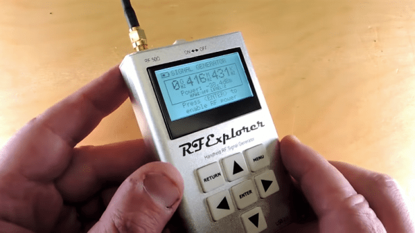
We usually reserve the honor of Fail of the Week for one of us – someone laboring at the bench who just couldn’t get it together, or perhaps someone who came perilously close to winning a Darwin Award. We generally don’t highlight commercial products in FotW, but in the case of this substandard RF signal generator, we’ll make an exception.

We suppose the fail-badge could be pinned on [electronupdate] for this one in a way; after all, he did shell out $200 for the RF Explorer signal generator, which touts coverage from 24 MHz to 6 GHz. But in true lemons-to-lemonade fashion, the video below he provides us with a thorough analysis of the unit’s performance and a teardown of the unit.

The first step is a look at the signal with a spectrum analyzer, which was not encouraging. Were the unit generating a pure sine wave as it should, we wouldn’t see the forest of spikes indicating harmonics across the band. The oscilloscope isn’t much better; the waveform is closer to a square wave than a sine. Under the hood, he found a PIC microcontroller and a MAX2870 frequency synthesizer, but a conspicuous absence of any RF filtering components, which explains how the output got so crusty. Granted, $200 is not a lot to spend compared to what a lab-grade signal generator with such a wide frequency range would cost. And sure, external filters could help. But for $200, it seems reasonable to expect at least some filtering.

We applaud [electronupdate] for taking one for the team here and providing some valuable tips on RF design dos and don’ts. We’re used to seeing him do teardowns of components, like this peek inside surface-mount inductors, but we like thoughtful reviews like this too.

Continue reading “Fail Of The Week: How Not To Design An RF Signal Generator”

Signal Generator Uses FPGA

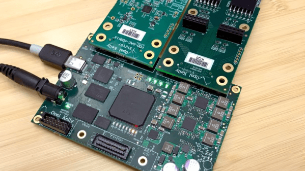
Although there are a few exceptions, FPGAs are predominantly digital devices. However, many FPGA applications process analog data, so you often see an FPGA surrounded by analog and digital converters. This is so common that Opal Kelly — a producer of FPGA tools — launched the SYZYGY open standard for interconnecting devices like that. [Armeen] — a summer intern at Opal Kelly — did a very interesting open source FPGA-based signal generator using a Xilinx FPGA, and a SYZYGY-compliant digital to analog converter.

As you might expect, [Armeen] used a lot of Opal Kelly hardware and software in the project. But the Verilog code (available on GitHub) shows a lot of interesting things including some very practical example code for using Xilinx CORDIC IP,  which is a great way to do high-order math using digital logic.

Continue reading “Signal Generator Uses FPGA”

Smartphone Bench Instrument Apps: Disappointment Or Delight?

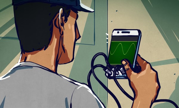
If you are interested in electronics or engineering, you’ll have noticed a host of useful-sounding apps to help you in your design and build work. There are calculators, design aids, and somewhat intriguingly, apps that claim to offer an entire instrument on your phone. A few of them are produced to support external third-party USB instrument peripherals, but most of them claim to offer the functionality using just the hardware within the phone. Why buy an expensive oscilloscope, spectrum analyzer, or signal generator, when you can simply download one for free?

Those who celebrate Christmas somewhere with a British tradition are familiar with Christmas crackers and the oft-disappointing novelties they contain. Non-Brits are no doubt lost at this point… the crackers in question are a cardboard tube wrapped in shiny paper drawn tight over each end of it. The idea is that two people pull on the ends of the paper, and when it comes apart out drops a toy or novelty. It’s something like the prize in a Cracker Jack Box.

Engineering-oriented apps follow this cycle of hope and disappointment. But there are occasional exceptions. Let’s tour some of the good and the bad together, shall we?

Continue reading “Smartphone Bench Instrument Apps: Disappointment Or Delight?”

Yet Another Inductance Measuring Scheme

How do you measure the value of an unknown inductor? If you have an LCR bridge or meter, you are probably going to use that. If not, there are many different techniques you can use. All of them rely on the same thing my Algebra teacher Mr. Harder used to say back in the 1970’s: you have to use what you know to get what you don’t know.

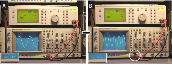
[Ronald Dekker] must think the same way. He took a 50-ohm signal generator and a scope. He puts the signal output to about 20kHz and adjusts for 1V peak-to-peak on the scope. Then he puts the unknown inductor across the signal and adjusts the frequency (and only the frequency) for an output of 1/2 volt peak-to-peak.

Continue reading “Yet Another Inductance Measuring Scheme”

Turntable Turns Waveform Generator

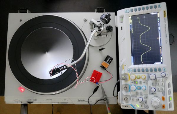
In need of a waveform generator for another project, [David Cook] crammed out the old turntable to modify it for a handy hack: By adding a simple reflectance sensor to the pickup he turned it into a waveform generator that optically plays back arbitrary waveforms from printed paper discs.

Continue reading “Turntable Turns Waveform Generator”

Retrotechtacular: TV Troubleshooting

As technology advances, finding the culprit in a malfunctioning device has become somewhat more difficult. As an example, troubleshooting an AM radio is pretty straightforward. There are two basic strategies. First, you can inject a signal in until you can hear it. Then you work backwards to find the stage that is bad. The other way is to trace a signal using a signal tracer or an oscilloscope. When the signal is gone, you’ve found the bad stage. Of course, you still need to figure out what’s wrong with the stage, but that’s usually one or two transistors (or tubes) and a handful of components.

A common signal injector was often a square wave generator that would generate audio frequencies and radio frequency harmonics. It was common to inject at the volume control (easy to find) to determine if the problem was in the RF or audio sections first. If you heard a buzz, you worked backwards into the RF stages. No buzz indicated an audio section problem.

A signal tracer was nothing more than an audio amplifier with a diode demodulator. Starting at the volume control was still a good idea. If you heard radio stations through the signal tracer, the RF section was fine. Television knocked radio off of its pedestal as the primary form of information and entertainment in most households, and thus the TV repair industry was created.

Continue reading “Retrotechtacular: TV Troubleshooting”

Arduino Masters Ham Radio Digital Mode

[jmilldrum] really gets a lot of use out of his Si5351A breakout board. He’s a ham [NT7S], and the Si5351A can generate multiple square waves ranging from 8 kHz to 160 MHz, so it only stands to reason that it is going to be a useful tool for any RF hacker. His most recent exploit is to use the I2C-controllable chip to implement a Fast Simple QSO (FSQ) beacon with an Arduino.

FSQ is a relatively new digital mode that uses a form of low rate FSK to send text and images in a way that is robust under difficult RF propagation. There are 32 different tones used for symbols so common characters only require a single tone. No character takes more than two tones.

Continue reading “Arduino Masters Ham Radio Digital Mode”