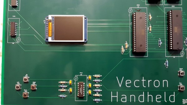
Recreating the arcade smash hit Pong in a device small enough to plug into a home television was a considerable technical challenge back in 1975. Of course, a big part of that was the fact that it needed to be cheap enough that consumers would actually buy it. But had money been no object, the Vectron Handheld by [Nick Bild] shows what a dedicated Pong board based on the 6502 CPU and 7400-series logic could have looked like.
Well, aside from the display anyway. While [Nick] made sure to use components that were contemporaries of the 6502 wherever possible, he did drop in a modern SPI LCD panel. After all, it’s supposed to be a portable game system.
Though as you can see in the video after the break, the massive 273 mm x 221 mm PCB only just meets that description. Incidentally, there’s no technical reason for the board to be this big; [Nick] was just playing it safe as he’s still learning KiCad.
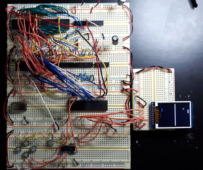
Those with a keen eye towards 6502 projects likely saw the breadboard version of the Vectron that [Nick] put together last year. Compared to the original, the circuit for the handheld has been considerably simplified as it wasn’t designed to be a general purpose 6502 computer. Whether or not you think being able to play Pong on it makes up for those shortcomings is a matter of personal preference.